Automatic debugging device of intelligent data collection instrument

A technology for smart meters and data acquisition, applied in measuring devices, instruments, etc., can solve the problems of low accuracy and stability of technical parameters, long development cycle of data acquisition smart meters, etc.

Inactive Publication Date: 2015-04-29
XUZHOU NORMAL UNIVERSITY
View PDF5 Cites 0 Cited by
  • Summary
  • Abstract
  • Description
  • Claims
  • Application Information

AI Technical Summary

Problems solved by technology

[0005] The purpose of the present invention is to solve the problems of long development period and low technical parameter accuracy and stability of data acquisition intelligent instruments, and propose a device for automatic debugging of data acquisition intelligent instruments, so as to automate the development and debugging of data acquisition intelligent instruments. Configure the technical parameters of data acquisition smart meters, automatically detect and verify

Method used


Image

  • Automatic debugging device of intelligent data collection instrument
  • Automatic debugging device of intelligent data collection instrument
  • Automatic debugging device of intelligent data collection instrument

Examples


Embodiment Construction

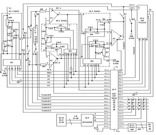
[0051] 1. Circuit connection instructions. exist figure 1 Among them, the three dotted boxes IC1, IC2, and IC3 are three chips of the model X9241, the internal structure of the chip and the pin connection, each chip has four digital potentiometers POT0, POT1, POT2, POT3, POT0 of IC2 , POT1 and POT2 are respectively represented by R2, R1 and R3, POT0, POT1, POT2 and POT3 in IC3 are represented by R6, R4, R5 and R7 respectively, H1, H2 and H3 represent the control and data of IC1, IC2 and IC3 respectively Register; K1-K8 consists of IC7 and IC8 chips with model number HD74HC4066;

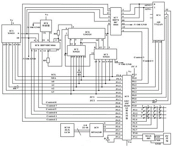
[0052] exist figure 2In IC1, pin 3 is connected to pin 17 and then Vc, pin 1 is connected to pin 7, pin 2 is connected to pin 18 and then connected to -VOR GND, pin 6 is connected to pin 13 and then the common center tap VW12 is connected, pin 8 is connected to pin 12, pin 11 Pin 19, pin 10 -VOR GND, pin 20, pin 3 Vc; P1.0, P1.1, P1.2, P1.3 negate, P1.4, P1.5 of IC5 are connected to IC1 The 15, 5...


PUM


Abstract

The invention relates to an automatic debugging device of an intelligent data collection instrument. The automatic debugging device comprises an X9241 type digital potentiometer, an operational amplifier LM324, a data amplifier composed of an operational amplifier A1, an operational amplifier A2 and an operational amplifier A3 and a processor STC15F2KS2. The processor STC15F2KS2 controls an electronic switch in an HD74HC4066 to be connected and disconnected, one of two paths of signals output by a sensor IC0 or a sensor IC1 is selected to be sent to the data amplifier, one of two paths of signals output by the A3 or the IC1 is selected to be sent to an AD7712AN, the IC1 is used for outputting high-precision linear voltages to detect the linearity of the data amplifier and the linearity of an ADC of a sample machine, a standard part full range loaded on the sensor IC0 and values output by an IC4 in the no-load process are tested, a standard part is loaded on the IC0 many times, the IC4 outputs the corresponding digital quantity, therefore, experimental data are obtained, and a function relationship of the data is built. According to the device, the development period of the intelligent data collection instrument is shortened, labor intensity of development personnel is reduced, and the stability of the intelligent data collection instrument is improved.

Description

technical field [0001] The invention relates to an intelligent instrument debugging device, in particular to an automatic debugging device for an intelligent instrument for collecting data such as sensor output analog quantities, and belongs to the technical field of developing measuring instruments. Background technique [0002] The application of Internet of Things technology has promoted the development of data acquisition smart instrument technology. At present, the smart meters produced in the United States, Germany and Japan have advanced technology, high precision and resolution, and reliable performance. The key technologies of instruments; some advanced techniques and methods have been adopted in the development and production of smart meters in China, and some key technologies have also been mastered, but the overall quality of smart meters still has a certain gap compared with developed countries. [0003] Data acquisition smart instruments generally include hard...

Claims


Application Information

Patent Timeline
IPC IPC(8): G01D18/00G01D21/00
Inventor 吕俊怀
Owner XUZHOU NORMAL UNIVERSITY
Why Eureka
Try Eureka