
An axial continuous temperature and pressure measurement device for fluid in a pipe

A pressure measuring device and internal fluid technology, applied to measuring devices, instruments, etc., can solve problems such as long dynamic response time, complex structure of measuring devices, and affecting the working state of fluids, and achieve low operation and maintenance costs, reliable measurement technology, and measurement The effect of structural simplification

Active Publication Date: 2017-01-11
GUANGXI UNIV
View PDF6 Cites 0 Cited by
  • Summary
  • Abstract
  • Description
  • Claims
  • Application Information

AI Technical Summary

Problems solved by technology

Most of the traditional methods are to measure the temperature and pressure of the inlet and outlet of the container fixedly; when some measure the pressure of the fluid in the container, a thin tube is arranged axially inside and a pressure hole is opened, and the pressure tube is moved to Time-sharing measurement of axial steady-state pressure has the disadvantages of high pressure leakage, large error, long dynamic response time, and large pressure measuring device that affects the working state of the fluid.
In some studies, when measuring the flow state of the fluid inside the container, dense measuring points are set in the measuring system, which can only measure the temperature, and measures must be taken to reduce the mutual influence between the temperature measuring points. Such a measuring device has a complex structure. high cost
For the fluid flow process in the container is complex, there are flow states such as phase change, turbulence, shock wave, etc., it is difficult to measure the temperature and pressure of several points to reflect the real flow of the fluid

Method used


Image

  • An axial continuous temperature and pressure measurement device for fluid in a pipe
  • An axial continuous temperature and pressure measurement device for fluid in a pipe
  • An axial continuous temperature and pressure measurement device for fluid in a pipe

Examples


Embodiment Construction

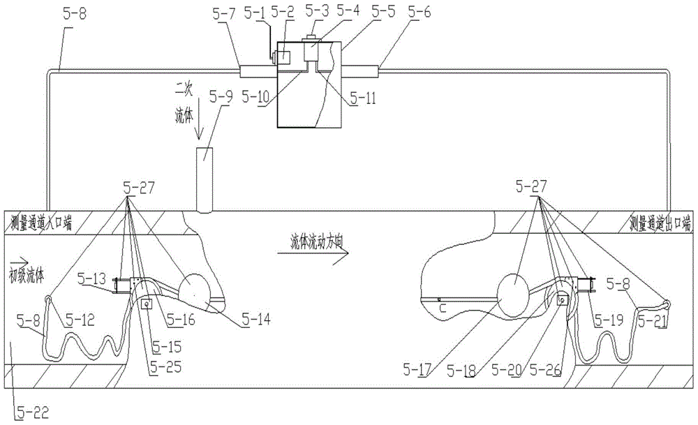
[0036] The present invention will be further described below in conjunction with the accompanying drawings and specific implementation.

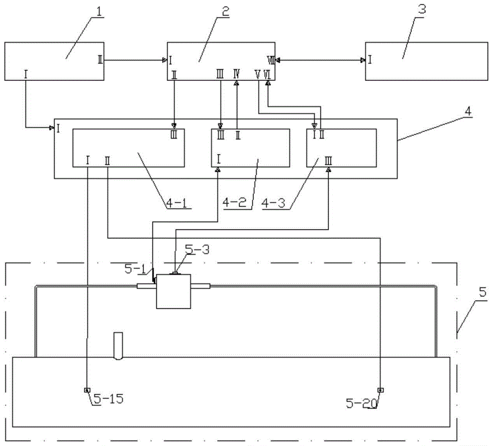
[0037] The structure of an axial continuous temperature and pressure measurement device for fluid in a pipe is as follows: figure 1 As shown, it consists of power supply 1, micro control unit 2, upper computer 3, drive acquisition module 4 and measurement section 5:

[0038] 1. The structure of each part:

[0039] 1) The power supply 1 is provided with interface I and interface II.

[0040] 2) The micro-control unit 2 is equipped with a power supply interface I, a drive module control interface II, a pressure measurement command transmission interface III, a pressure data reception interface IV, a temperature measurement command transmission interface V, a temperature data reception interface VI, and a host computer signal transmission interface , Receiving interface VII.

[0041] 3) The upper computer 3 is provided with an upper computer...


PUM


Abstract

The invention discloses an axial temperature and pressure continuous measuring device for fluid in a pipe. The axial temperature and pressure continuous measuring device is composed of a power supply, a micro control unit, an upper computer, a driving acquisition module and a measuring section. Compared with the prior art, the axial temperature and pressure continuous measuring device has the advantages that a mobile measuring unit is completely sealed in a measuring channel, so that leakage does not exist; by the adoption of a mobile measuring method, the flowing condition of the fluid in a stable state can be measured without arranging multiple measuring points in the measuring channel, so that the measuring structure is simplified, and the influence on flowing of the fluid is small; technologies related to all the units are already mature, the measuring technology is reliable, a measured result is approximate to the true flowing state of the internal fluid, and the accuracy is high; the cost for operation and maintenance is low.

Description

technical field [0001] The invention belongs to the technical field of fluid flow state testing, in particular to an axial continuous temperature and pressure measurement device for fluid in a tube. Background technique [0002] In the research of fluid machinery such as injectors, hydraulic cylinders, and piston cylinders, flow state measurement is crucial to the optimization of their structures. Most of the traditional methods are to measure the temperature and pressure of the inlet and outlet of the container fixedly; when some measure the pressure of the fluid in the container, a thin tube is arranged axially inside and a pressure hole is opened, and the pressure tube is moved to The time-sharing measurement of axial steady-state pressure has the disadvantages of high pressure leakage, large error, long dynamic response time, and large pressure measuring device that affects the working state of the fluid. In some studies, when measuring the flow state of the fluid insid...

Claims


Application Information

Patent Timeline
Patent Type & Authority Patents(China)
IPC IPC(8): G01D21/02
Inventor 李刚段欢黄惠兰郑克敏
Owner GUANGXI UNIV
Learn More