A synchronous rolling forming device for dimpled heat transfer tubes

A technology for roll forming and heat transfer tubes, which is applied in the field of heat transfer tube processing and forming, can solve the problems of few extrusion forming devices, complicated work of replacing bare tubes, and high production costs

Active Publication Date: 2020-10-20
成都市成航发科技有限公司
View PDF10 Cites 0 Cited by
  • Summary
  • Abstract
  • Description
  • Claims
  • Application Information

AI Technical Summary

Problems solved by technology

However, although there are many kinds of heat transfer tube processing and manufacturing devices, there are currently few extrusion molding devices suitable for dimpled heat transfer tubes.
[0005] However, in recent years, some pitted tube manufacturing devices have been disclosed in China, such as: Patent No. "CN2017106146693" announced a stamping-type industrial high-efficiency tube forming table. Two columns of dimples, cannot form multiple dimples in the same section
Patent No. "CN2017106146640" discloses a multi-cylinder type dimple heat transfer tube extrusion molding device. When the device adjusts the dimple spacing, it needs to disassemble the device and then replace the extruded plate, so the dimple spacing parameter adjustment operation is complicated. ;In addition, when multiple hydraulic cylinders squeeze the light pipe, it is difficult to ensure the synchronous work of multiple hydraulic cylinders, resulting in small extrusion of the light pipe, inconsistent pit size and depth
Patent No. "CN201710614666X" discloses a staggered chrysalis heat transfer tube extrusion molding device, which can only form 6 dimples (that is, one pitch) at a time, and then needs to continue feeding, and then extrude the next pitch , so the production efficiency is low and the production cost is high
Patent No. "CN2017106146585" discloses a wedge-type dimpled heat transfer tube extrusion molding device, which also has the problem of inconvenient adjustment of dimple spacing; in addition, due to the asynchronous movement of the pressure plate, the tube is extruded eccentrically
Patent No. "CN201611051228.9" discloses a rolling forming device for dimpled heat transfer tubes. This device has disadvantages such as poor synchronous rolling forming effect and complicated replacement of bare tubes.

Method used


Image

  • A synchronous rolling forming device for dimpled heat transfer tubes
  • A synchronous rolling forming device for dimpled heat transfer tubes
  • A synchronous rolling forming device for dimpled heat transfer tubes

Examples


Embodiment Construction

[0034] The present invention will be described in further detail below in conjunction with the accompanying drawings.

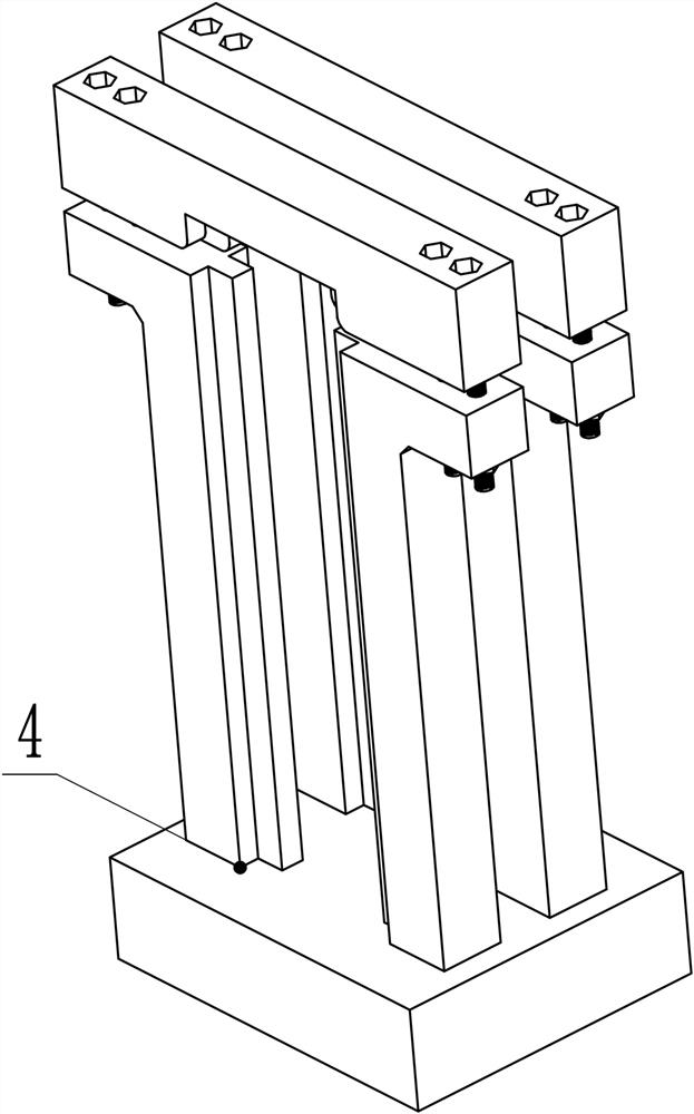
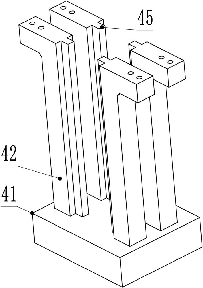
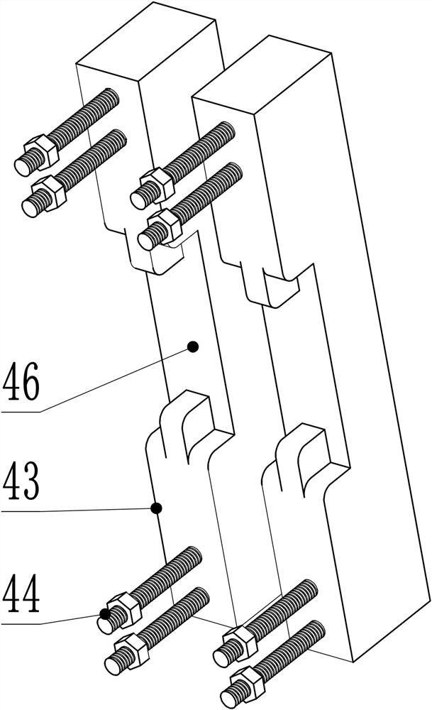
[0035] refer to Figure 1~Figure 2 , a synchronous rolling forming device for pit heat transfer tubes, which consists of a transmission system 1, a rolling system 2, a guiding system 3, a clamping system 4, and an auxiliary system 5. The assembly relationship is as follows: the rolling system 2 is sleeved on the outer side of the middle of the driving gear shaft 11 of the transmission system 1, and the guiding system 3 is sleeved on the outer sides of the two ends of the driving gear shaft 11, and the guiding system 3 is installed on the clamping system through the guiding groove 34. 4, the left and right sides of the clamping system 4 are respectively designed with auxiliary systems 5.

[0036] The working principle is: the motor drives the reducer to rotate, the reducer drives the transmission system 1 to rotate, and the transmission system 1 drives the ro...


PUM


Abstract

The invention relates to a synchronous rolling and forming device for pit heat transfer tubes. The synchronous rolling and forming device is composed of a transmission system, a rolling system, a guide system, a clamping system and the auxiliary systems, and is characterized in that the rolling system sleeves the middle part of a driving gear shaft of the transmission system, the guiding systems sleeve the two end parts of the driving gear shaft and are installed in the clamping system via the guiding grooves, and the auxiliary systems are designed at the left side and the right side of the clamping system respectively. During work, the transmission system drives the rolling system to rotate, and the rolling system rotates to drive a pressing head to roll a light tube to form a pit tube. Compared with the prior art, the pressing head can synchronously extrude the light tube, the eccentric extrusion of the light tube is prevented, and then the consistency of the sizes, the depths, the distances and the shapes of the pits is ensured. In addition, the parts of the synchronous rolling and forming device are all mechanical parts and are not hydraulic elements, so that the synchronous rolling and forming device is safe and reliable, and the problems of hydraulic oil leakage and the asynchronous movement of the hydraulic cylinders are solved.

Description

technical field [0001] The invention relates to the field of processing and forming of heat transfer tubes, in particular to a synchronous roll forming device for dimpled heat transfer tubes. Background technique [0002] Heat transfer is a very common natural phenomenon and a common process in industries such as power, nuclear energy, electronics, transportation, refrigeration, chemical, petroleum, aerospace, etc. The heat exchanger occupies a key position in the above-mentioned industries. The heat exchanger is not only an indispensable part to ensure the normal operation of the entire engineering equipment, but also occupies an important share in the entire project in terms of metal consumption, power consumption and capital investment. . Taking a power plant as an example, if the boiler is also used as heat exchange equipment, the capital investment of the heat exchanger accounts for about 70% of the total investment of the power plant; in petrochemical industry, the in...

Claims


Application Information

Patent Timeline
Patent Type & Authority Patents(China)
IPC IPC(8): B21C23/21
CPCB21C23/211B21C23/212B21C23/217
Inventor 谢帅郭正伟董超群任连城龚银春
Owner 成都市成航发科技有限公司
Why Eureka
Try Eureka