Hydraulic sliding table brake device for vehicle sliding table test

A brake device and testing technology, applied in the field of automobile crash test, to achieve the effect of fast response and simple structure

Active Publication Date: 2015-04-29
ZHEJIANG GEELY AUTOMOBILE RES INST CO LTD +1
View PDF7 Cites 0 Cited by
  • Summary
  • Abstract
  • Description
  • Claims
  • Application Information

AI Technical Summary

Problems solved by technology

However, the existing hydraulic servo brake system cannot meet the above requirements

Method used


Image

  • Hydraulic sliding table brake device for vehicle sliding table test
  • Hydraulic sliding table brake device for vehicle sliding table test
  • Hydraulic sliding table brake device for vehicle sliding table test

Examples


Embodiment Construction

[0025] In order to make the objectives, technical solutions and advantages of the present invention clearer, the embodiments of the present invention will be further described below with reference to the accompanying drawings.

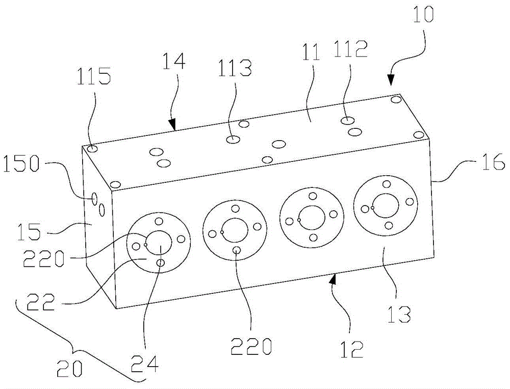
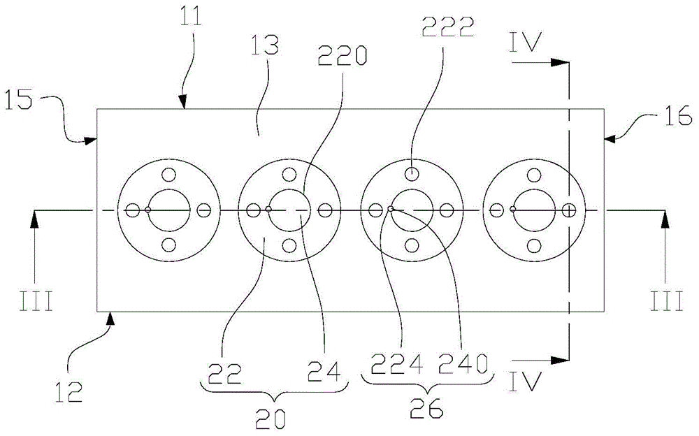
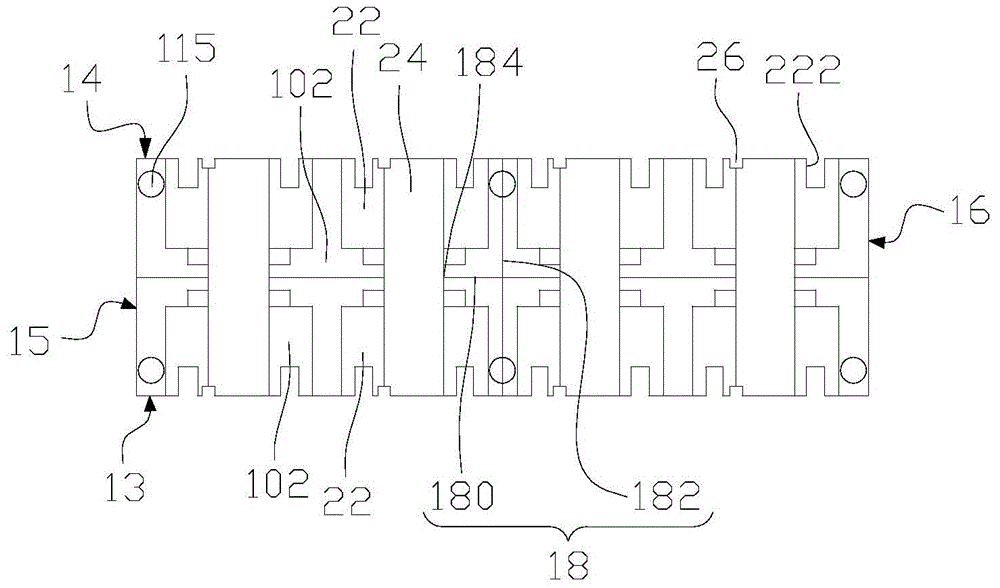
[0026] Please refer to Figure 1-4 , The hydraulic slide brake device for vehicle slide test provided by the embodiment of the present invention includes a hydraulic cylinder 10 and at least two piston pieces 20 . The hydraulic cylinder 10 is in the shape of a rectangular parallelepiped, and includes a top plate 11 , a bottom plate 12 , a front side plate 13 , a rear side plate 14 , a left side plate 15 , a right side plate 16 and a partition plate 18 . The baffle 18 includes a first sub-baffle 180 parallel to the front side plate 13 and a second sub-baffle 182 parallel to the left side plate 15 . The number of the first sub-partitions 180 is one, and the number of the second sub-partitions 182 is at least one. The first sub-partitions 180 and each of...


PUM


Abstract

The invention discloses a hydraulic sliding table brake device for a vehicle sliding table test. The hydraulic sliding table brake device comprises a hydraulic cylinder and at least two piston parts, wherein the hydraulic cylinder is cuboid-shaped and comprises a top plate, a bottom plate, a front side plate, a rear side plate, a left side plate, a right side plate, a first sub-partition and a second sub-partition; the first sub-partition and the second sub-partition are connected in a cross shape; the hydraulic cylinder is equally divided into a plurality of piston cavities; the piston cavities are grouped in pairs; each group of piston cavities includes two piston cavities arranged in a length extending direction of the left side plate; at least one piston part is mounted in the group of piston cavities; an oil inlet is formed in the top plate; through holes in one-to-one correspondence with the piston parts are formed in the first sub-partition at intervals; each piston part comprises two pistons and a piston rod for connecting the pistons, the piston rod penetrates through the corresponding through hole in the first sub-partition, and the pistons are positioned in the piston cavities in the group of piston cavities and can penetrate through the front side plate and the rear side plate respectively. The hydraulic sliding table brake device can bidirectionally move and is high in response speed.

Description

technical field [0001] The invention relates to the technical field of automobile collision test, in particular to a hydraulic sliding table braking device for vehicle sliding table test. Background technique [0002] The development of the automobile industry has brought great convenience to people's lives and has become a major driving force and opportunity for the economic development of various countries. At the same time, automobiles also have a great negative impact on human society, which is the constant occurrence of traffic accidents, car exhaust that pollutes the environment and the energy crisis caused by automobile fuel. Among them, car safety is the most directly related to people's lives. Vehicle safety has a huge impact on the life safety of occupants and pedestrians outside the vehicle. The safety restraint system plays a key role in the safety of the vehicle, and the matching of the safety restraint system is usually completed in the sliding table system t...

Claims


Application Information

Patent Timeline
Patent Type & Authority Applications(China)
IPC IPC(8): G01M7/08G01M17/007
Inventor 柳惠君金恩宇栾朋曹国华李月明韩刚刘卫国吴成明冯擎峰
Owner ZHEJIANG GEELY AUTOMOBILE RES INST CO LTD
Why Eureka
Try Eureka