
An Inertial Impact Linear Piezoelectric Motor Based on Cantilever Beam Structure

An inertial impact, piezoelectric motor technology, applied in the direction of piezoelectric effect/electrostrictive or magnetostrictive motors, electrical components, generators/motors, etc. High, difficult to assemble, etc., to achieve the effect of stable and accurate step distance, improved displacement resolution, and suitable load capacity

Active Publication Date: 2021-08-24
HEFEI UNIV OF TECH
View PDF5 Cites 0 Cited by
  • Summary
  • Abstract
  • Description
  • Claims
  • Application Information

AI Technical Summary

Problems solved by technology

The inertial impact motor developed by Qiaosheng Pan et al., University of Science and Technology of China, is designed as an H-like structure, imitating the movements of hands and feet when climbing rocks to complete the overall one-way movement, but the structure is complex, with as many as 21 parts, and most of them are tightened by bolts. Solid fit is not easy to assemble, and it can only realize one-way movement. Its displacement resolution is 17.8 μm, and the displacement resolution is not high

Method used


Image

  • An Inertial Impact Linear Piezoelectric Motor Based on Cantilever Beam Structure
  • An Inertial Impact Linear Piezoelectric Motor Based on Cantilever Beam Structure
  • An Inertial Impact Linear Piezoelectric Motor Based on Cantilever Beam Structure

Examples


Embodiment Construction

[0024] The present invention will be further described through the embodiments below in conjunction with the accompanying drawings.

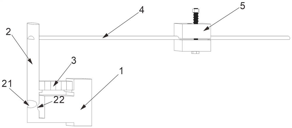
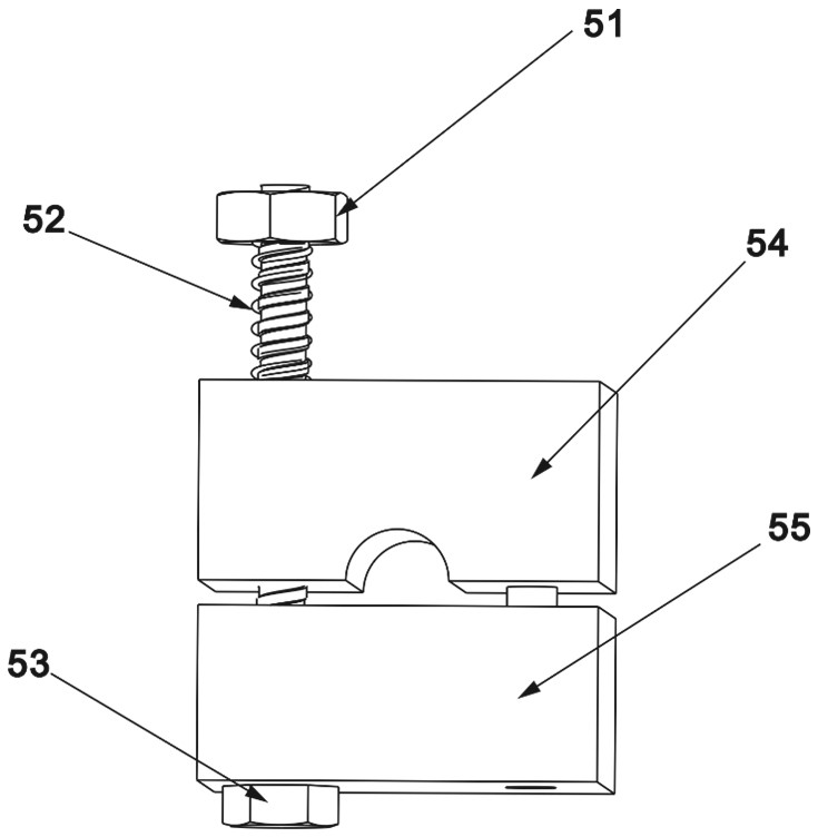
[0025] see figure 1 , an inertial impact linear piezoelectric motor based on a cantilever beam structure includes a base 1 , a pole 2 , a piezoelectric stack 3 , a guide rail 4 and a moving slider 5 .

[0026] Depend on figure 1 It can be seen that the base 1 is in the shape of an angle steel block, and the lower part of the outer end of the horizontal block of the base 1 is fixedly connected with the lower end of the vertical rod 2 .

[0027] The vertical rod 2 is a cylindrical rod that is elliptical in cross section; a flexible hinge is provided at the near lower end of the vertical rod 2, and the flexible hinge is composed of an outer groove 21 and an inner groove 22 that are cross-sectionally arc-shaped, and the outer groove 21 and the inner groove 22 are arc grooves with the same radius, and the distance between the outer groove 21 and th...


PUM


Abstract

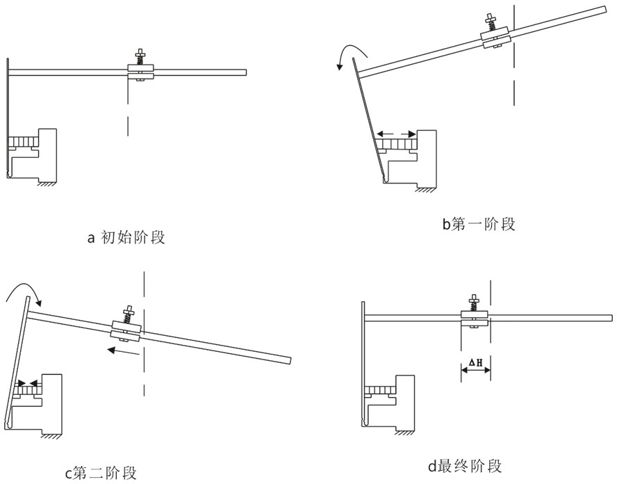
The invention relates to an inertial impact linear piezoelectric motor based on a cantilever beam structure, and belongs to the technical field of precision driving and positioning. It includes a base, a vertical rod, a piezoelectric stack, a guide rod and a moving slider; the lower part of the outer end of the horizontal block of the base is connected to the lower end of the vertical rod through a flexible hinge, and the upper part of the vertical rod is fixedly connected to one end of the guide rod. The other end of the rod is in the shape of a cantilever, and the moving slider is slidably fitted on the guide rod; the piezoelectric stack is located parallel to the top of the horizontal block of the base, and is fixedly connected between the middle of the vertical rod and the vertical block of the base; When working, the piezoelectric stack is not energized at the initial length; the piezoelectric stack is energized under the action of the positive sawtooth frequency voltage, which drives the upper part of the vertical rod to swing, and drives the moving slider to move along the guide rod by static friction; When the electric stack recovers to the initial length, the moving slider completes a step ΔH movement, and a positive periodic motion is completed at this time; under the action of the reverse sawtooth frequency voltage, the moving slider realizes the reverse movement.

Description

technical field [0001] The invention belongs to the technical field of precision driving and positioning, and in particular relates to an inertial impact linear piezoelectric motor. Background technique [0002] Piezoelectric motor is a kind of driving mechanism that uses inverse piezoelectric effect to convert electromechanical energy. Because of its superior characteristics, it is widely used in biomedical devices, precision positioning systems, electronic scanning technology and other fields. There are many structural styles of piezoelectric motors, which can be mainly divided into inertial impact motors, ultrasonic motors, and inchworm motors. [0003] Inertial impact piezoelectric motors, which use inertial impacts to achieve micro-displacement, are also known as "stick-slip actuators". The inertial impact motor developed by Qiaosheng Pan et al., University of Science and Technology of China, is designed as an H-like structure, imitating the movements of hands and feet...

Claims


Application Information

Patent Timeline
Patent Type & Authority Patents(China)
IPC IPC(8): H02N2/04H02N2/02
CPCH02N2/025H02N2/043
Inventor 贺良国严毅王勇赵小勇李新宇程子阳张勇高广杰郝赛
Owner HEFEI UNIV OF TECH
Learn More