Complete common-path type microchip laser feedback interferometer

A microchip laser and laser technology, used in instruments, optical devices, measuring devices, etc., can solve the problems of measuring optical signal crosstalk, affecting the working stability of feedback interferometers, unstable optical components, etc., to improve accuracy and stability. stability, eliminate the instability of the reference mirror, and suppress the effect of environmental interference

Active Publication Date: 2012-04-11
TSINGHUA UNIV
View PDF3 Cites 8 Cited by
  • Summary
  • Abstract
  • Description
  • Claims
  • Application Information

AI Technical Summary

Problems solved by technology

[0003] However, when using the quasi-common-channel microchip laser feedback interferometer to measure the displacement of the object to be measured, it is found that the reference mirror set in the quasi-common-channel microchip laser feedback interferometer is an extremely unstable optical component, which greatly affects the entire feedback. The working stability of the interferometer, and during the measurement, because the angle between the measurement feedback light and the reference feedback light is very small, the reference mirror shows a strong angle sensitivity when selecting the measurement feedback light and the reference feedback light degrees, that is, when the yaw angle or pitch angle of the reference mirror changes slightly, it is easy to cause crosstalk between the reference optical signal and the measurement optical signal

Method used


Image

  • Complete common-path type microchip laser feedback interferometer
  • Complete common-path type microchip laser feedback interferometer
  • Complete common-path type microchip laser feedback interferometer

Examples


Embodiment Construction

[0013] The present invention will be described in detail below in conjunction with the accompanying drawings and embodiments.

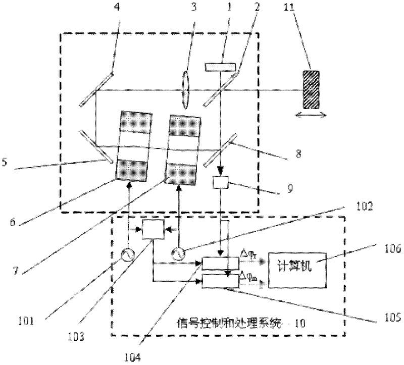
[0014] Such as figure 1 As shown, the present invention includes a microchip laser 1, and the laser light emitted by the microchip laser 1 propagates along an annular optical path (loop). A beam splitter 2, a converging lens 3 and a first total reflection mirror 4 are arranged successively on the reflected light path of the first beam splitter 2, and a second total reflection mirror 5 is arranged on the reflected light path of the first total reflection mirror 4, and the second total reflection mirror A first acousto-optic frequency shifter 6, a second acousto-optic frequency shifter 7, and a second beam splitter 8 are sequentially arranged on the reflection optical path of the mirror 5, and a photodetector 9 is arranged on the transmission optical path of the second beam splitter 8, wherein the second beam splitter The mirror 8 is on the transmitted...


PUM


Abstract

The invention relates to a complete common-path type microchip laser feedback interferometer which comprises a microchip laser, wherein a first spectroscope is arranged on an axis at an emitting end of the microchip laser; a first holophote is arranged on a reflected light path of the first spectroscope; a second holophote is arranged on the reflected light path of the first holophote; a first acousto-optic frequency shifter, a second acousto-optic frequency shifter and a second spectroscope are arranged on the reflected light path of the second holophote in turn; the second spectroscope is arranged on a transmission light path of the first spectroscope; a photoelectric detector is arranged on the transmission light path of the second spectroscope; a circular light path is formed by the first spectroscope, the first holophote, the second holophote, the first acousto-optic frequency shifter, the second acousto-optic frequency shifter and the second spectroscope; the laser emitted by the microchip laser once returns to a resonant cavity of the microchip laser through the circular light path, thereby modulating an output power of the laser and forming the reference feedback light; and the laser once passing by a circular path is reflected by a to-be-detected object and returns to the resonant cavity of the microchip laser through the circular light path again, thereby modulating the output power of the laser and forming the measuring feedback light. The complete common-path type microchip laser feedback interferometer can be widely applied to the unmatched target non-contact type accurate displacement measurement.

Description

technical field [0001] The invention relates to a microchip laser feedback interferometer, in particular to a completely common path microchip laser feedback interferometer used for non-contact precision displacement measurement of a non-cooperating target. Background technique [0002] Microchip lasers have extremely high sensitivity to optical feedback, and the combination of frequency-shifting optical feedback system and phase heterodyne measurement technology can realize motion displacement measurement with high displacement resolution. Because the entire feedback external cavity of ordinary microchip laser feedback interferometer is a dead path, the fluctuation of air refractive index, the deformation of components caused by temperature changes, and the instability of the laser itself will cause the phase drift of the external cavity of the feedback light, which will seriously affect Accuracy of displacement measurement. In order to eliminate the negative impact caused...

Claims


Application Information

Patent Timeline
Patent Type & Authority Applications(China)
IPC IPC(8): G01B9/02G01B11/02
Inventor 谈宜东任舟张松张书练
Owner TSINGHUA UNIV
Why Eureka
Try Eureka