A displacement sensor based on a gear rotary-type fiber Bragg raster and an application method thereof

A technology of grating displacement and sensor, which is applied in the direction of instruments, optical devices, measuring devices, etc., and can solve the problems that online displacement monitoring is susceptible to electromagnetic interference and has low accuracy

CN103644847AInactive Publication Date: 2014-03-19KUNMING UNIV OF SCI & TECH
5 Cites 9 Cited by

Patent Information

Authority / Receiving Office
CN · China
Patent Type
Applications(China)
Current Assignee / Owner
Publication Date
2014-03-19
Estimated Expiration
Not applicable · inactive patent

Smart Images

  • Figure 1
    Figure 1
  • Figure 2
    Figure 2
  • Figure 3
    Figure 3
Patent Text Reader

Abstract

The invention relates to a displacement sensor based on a gear rotary-type fiber Bragg raster and an application method thereof, and belongs to the technical field of photoelectron measurement. The displacement sensor of the invention comprises a fiber Bragg raster, a cantilever beam, a first gear, a second gear, a first tooth bar, a second tooth bar, a measurement contact head, a first rolling bearing, a second rolling bearing, a stepped shaft, a displacement space limiting sleeve pipe, a first tooth bar sleeve pipe, a second tooth bar sleeve pipe, a third tooth bar sleeve pipe, a first spring, a second spring, a metal box, an externally connected fiber, a bottom seat of the first rolling bearing and a bottom seat of the second rolling bearing, wherein the fiber Bragg raster, the cantilever beam, the first gear, the second gear, the first tooth bar, the second tooth bar, the first rolling bearing, the second rolling bearing, the stepped shaft, the first tooth bar sleeve pipe, the second tooth bar sleeve pipe, the third tooth bar sleeve pipe, the first spring, the second spring, the bottom seat of the first rolling bearing and the bottom seat of the second rolling bearing are packaged inside the bottom box. According to the displacement sensor based on the gear rotary-type fiber Bragg raster and the application method thereof of the invention, on-line monitoring of displacement is realized. At the same time, the structure is simple; the usage is convenient; the measuring range is large; the sensitivity is adjustable; and the anti-interference capability is strong.
Need to check novelty before this filing date? Find Prior Art

Description

technical field

[0001] The invention relates to a gear-rotating optical fiber Bragg grating displacement sensor and a using method thereof, which belong to the technical field of optoelectronic measurement. Background technique

[0002] In recent years, accidents such as bridge collapses, tunnel collapses, and landslides along the way have occurred frequently in China. Timely and accurate grasp of crack changes and relative position slippage in civil structures makes displacement detection particularly important. At present, the existing fiber grating displacement sensors generally fix the fiber grating on various elastic beams, convert the displacement to the strain of the grating through the deformation of the beam (shrapnel), and measure the corresponding displacement by demodulating the wavelength drift of the grating. This kind of sensor has high precision, anti-electromagnetic interference, stable chemical properties and can meet distributed measurement. The disadvanta...

Examples

Embodiment 1

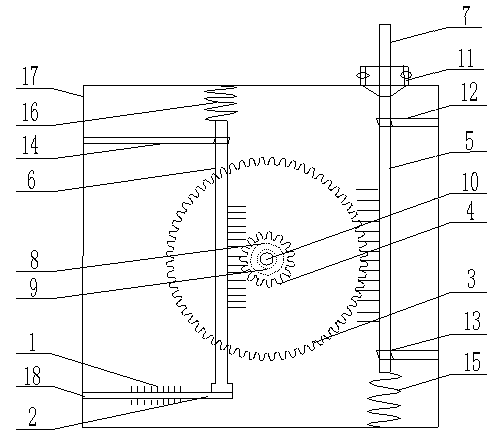
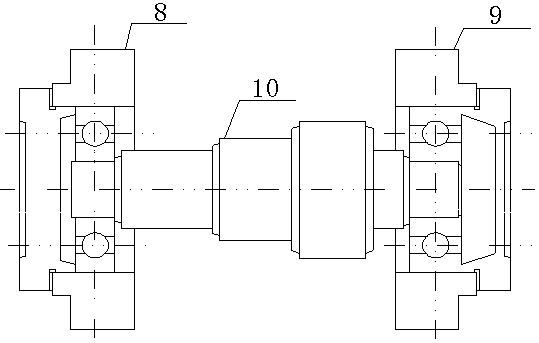
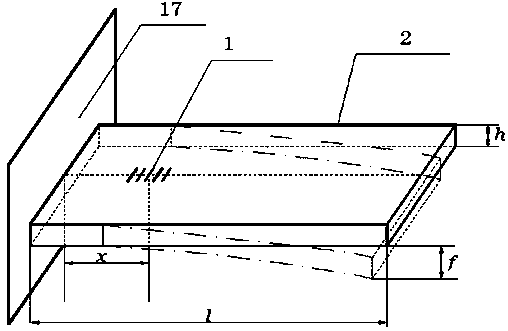
[0049] Embodiment 1: as Figure 1-3 As shown, a gear-based rotary optical fiber Bragg grating displacement sensor includes optical fiber Bragg grating 1, cantilever beam 2, gear I3, gear II4, rack I5, rack II6, measuring contact head 7, rolling bearing I8, rolling bearing II9, Step shaft 10, displacement limit sleeve 11, rack sleeve I12, rack sleeve II13, rack sleeve III14, spring I15, spring II16, metal box 17, external optical fiber 18, rolling bearing I base and rolling bearing II base ; Among them, fiber Bragg grating 1, cantilever beam 2, gear Ⅰ 3, gear Ⅱ 4, rack Ⅰ 5, rack Ⅱ 6, rolling bearing Ⅰ 8, rolling bearing Ⅱ 9, stepped shaft 10, rack bushing Ⅰ 12, rack bushing Ⅱ 13, rack sleeve Tube III 14, spring I 15, spring II 16, rolling bearing I base and rolling bearing II base are packaged inside the metal box 17, and the fiber Bragg grating 1 is pasted on the central axis of the upper and lower surfaces of the cantilever beam 2 and leads out of the rectangular metal box 17...

Embodiment 2

[0053] Embodiment 2: as Figure 1-3 As shown, a gear-based rotary optical fiber Bragg grating displacement sensor includes optical fiber Bragg grating 1, cantilever beam 2, gear I3, gear II4, rack I5, rack II6, measuring contact head 7, rolling bearing I8, rolling bearing II9, Step shaft 10, displacement limit sleeve 11, rack sleeve I12, rack sleeve II13, rack sleeve III14, spring I15, spring II16, metal box 17, external optical fiber 18, rolling bearing I base and rolling bearing II base ; Among them, fiber Bragg grating 1, cantilever beam 2, gear Ⅰ 3, gear Ⅱ 4, rack Ⅰ 5, rack Ⅱ 6, rolling bearing Ⅰ 8, rolling bearing Ⅱ 9, stepped shaft 10, rack bushing Ⅰ 12, rack bushing Ⅱ 13, rack sleeve Tube III 14, spring I 15, spring II 16, rolling bearing I base and rolling bearing II base are packaged inside the metal box 17, and the fiber Bragg grating 1 is pasted on the central axis of the upper and lower surfaces of the cantilever beam 2 and leads out of the rectangular metal box 17...