
Medical film viewer capable of longitudinal and transverse orientation

A technology of horizontal positioning and film viewing lamps, which is applied in the direction of optical components, optics, instruments, etc., can solve the problems of strong flickering of light boxes, insufficient information display, and short life of ordinary fluorescent tubes, so as to facilitate long-term observation and improve accuracy Interpretation rate effect

Inactive Publication Date: 2015-04-29
NANTONG KANGSHENG MEDICAL EQUIP
View PDF12 Cites 6 Cited by
  • Summary
  • Abstract
  • Description
  • Claims
  • Application Information

AI Technical Summary

Problems solved by technology

[0004] 1. The film viewing light with low brightness will intercept the density image recorded by the film lock, so that the information recorded by the film lock cannot be fully displayed, and the film reading is inaccurate, thus increasing the chance of missed diagnosis or misdiagnosis;
[0005] 2. The light source of the box-type film viewer is generally provided by a fluorescent tube, which causes the light box to flicker strongly, and long-term use will cause damage to the doctor's eyes;
[0006] 3. The box is thick and clumsy, which is not conducive to placement or installation, and takes up a lot of office space;
[0007] 4. Using AC 220V direct input, there are hidden dangers to personal safety;
[0008] 5. The power consumption is relatively large, which does not conform to the concept of energy saving;
[0009] 6. Ordinary fluorescent tubes have a short service life, only about 1500 hours in normal use, but they are often damaged in actual use
Furthermore, even if the area with the cause of the disease is found, it is easy to see another similar area without paying attention, leading to misdiagnosis
Therefore, the problem that this medical film viewing light box exists is that it is inconvenient to fix the required area

Method used


Image

  • Medical film viewer capable of longitudinal and transverse orientation
  • Medical film viewer capable of longitudinal and transverse orientation
  • Medical film viewer capable of longitudinal and transverse orientation

Examples


Embodiment Construction

[0035] The present invention will be further explained below in conjunction with the accompanying drawings and specific embodiments.

[0036] It should be understood that the following specific embodiments are only used to illustrate the present invention but not to limit the scope of the present invention. It should be noted that these drawings are all simplified schematic diagrams, and only schematically illustrate the basic structure of the present invention, so they only show the configurations related to the present invention.

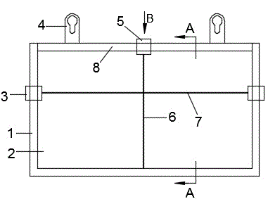
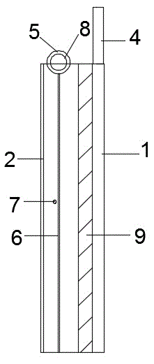
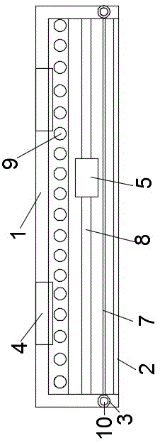
[0037] It can be seen from the accompanying drawings that the medical film viewing lamp capable of vertical and horizontal positioning includes a light frame 1, which is in a rectangular shape, and a frame and a back frame are arranged around the light frame 1. The light frame 1 A light frame plate is arranged on one side surface of the light frame plate, and a light-transmitting sheet 2 is arranged on the opposite side surface of the light frame ...


PUM


Abstract

The invention discloses a medical film viewer capable of longitudinal and transverse orientation, wherein a lamp frame plate is arranged on one side surface of a lamp frame; a transparent plate is arranged on the side surface opposite to the lamp frame plate; several lamp tubes are arranged between the lamp frame plate and the transparent plate; a top rod is arranged at the top of the lamp frame; several longitudinal line adjusting rings are arranged on the top rod in a penetrating manner, wherein a longitudinal line is fixedly arranged under each longitudinal adjusting ring; side rods are symmetrically arranged on both sides of the lamp frame respectively; each side rod is provided with several transverse line adjusting rings in a penetrating manner; and transverse lines are fixedly arranged between longitudinal line adjusting rings respectively at the same height on two side rods. According to the medical film viewer capable of longitudinal and transverse orientation, the reference of longitudinal and transverse lines can be provided, and the observation needs of various X-ray photographic plates or CT imaging plates can be satisfied on the premise of ensuring functions of normal film viewers.

Description

technical field [0001] The invention relates to a medical film viewer capable of longitudinal and lateral positioning, and belongs to the technical field of medical auxiliary equipment. Background technique [0002] The medical film viewing lamp is an auxiliary medical device used to assist in reading the image information on the X-ray photographic film and CT imaging film. When in use, turn on the light, and stick the X-ray photographic film and CT imaging film With the help of the lighting effect of the light, the light passes through or shines on the X-ray photographic film and CT imaging film, and the images on the X-ray photographic film and CT imaging film are clearly presented, which is convenient for doctors to observe clearly. [0003] At present, the X-ray photographic film and CT imaging film viewing lamps commonly used in domestic medical institutions are all traditional box-type, and both have the following defects: [0004] 1. The film viewing light with low b...

Claims


Application Information

Patent Timeline
IPC IPC(8): G02B27/02
CPCG02B27/024
Inventor 戴卫泽戴卫东毛德许刘顺南王亚菊
Owner NANTONG KANGSHENG MEDICAL EQUIP
Learn More