
Display apparatus

一种显示装置、显示单元的技术,应用在照明装置、照明装置的零部件、照明和加热设备等方向,能够解决不便等问题,达到小体积、解决亮暗不均、提升显示质量的效果

Inactive Publication Date: 2015-04-29
E INK HLDG INC
View PDF6 Cites 8 Cited by
  • Summary
  • Abstract
  • Description
  • Claims
  • Application Information

AI Technical Summary

Problems solved by technology

[0005] This shows that the above-mentioned existing display device obviously still has inconvenience and defects in structure and use, and needs to be further improved urgently.

Method used


Image

  • Display apparatus
  • Display apparatus
  • Display apparatus

Examples


Embodiment Construction

[0045] In order to further explain the technical means and effects of the present invention to achieve the intended purpose of the invention, the specific implementation, structure, features and effects of the display device proposed according to the present invention will be described in detail below in conjunction with the accompanying drawings and preferred embodiments. The description is as follows.

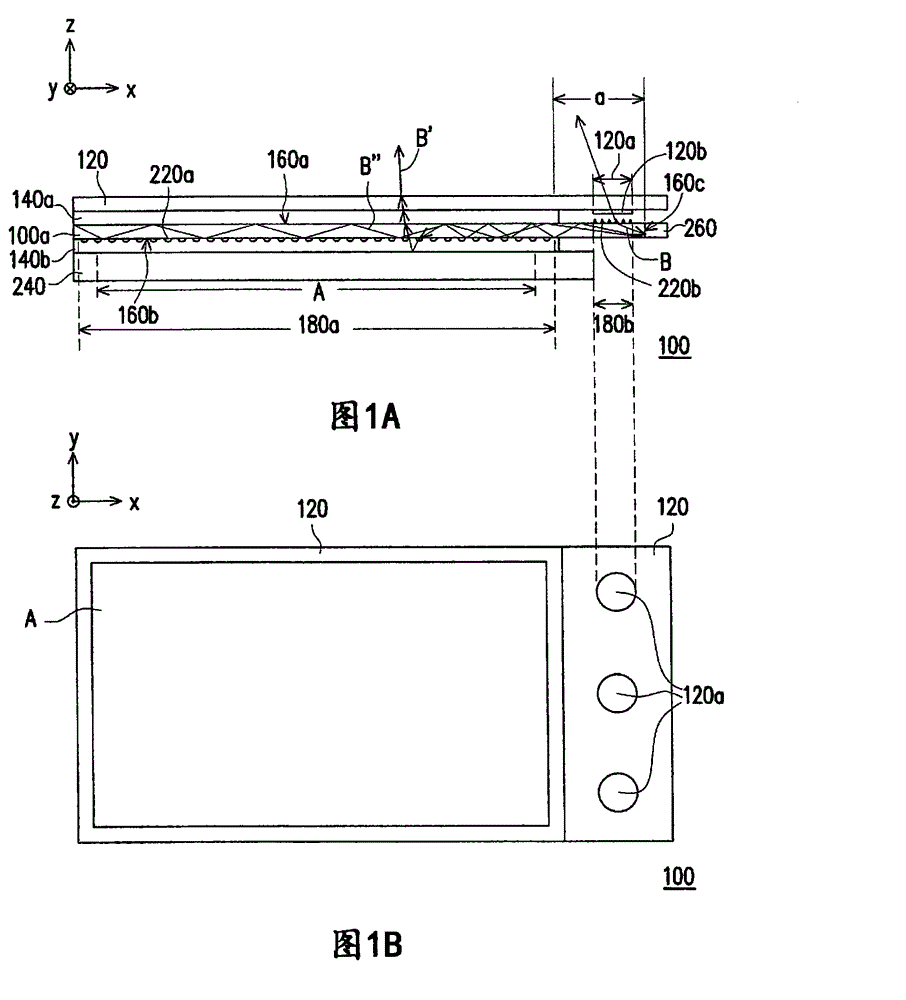
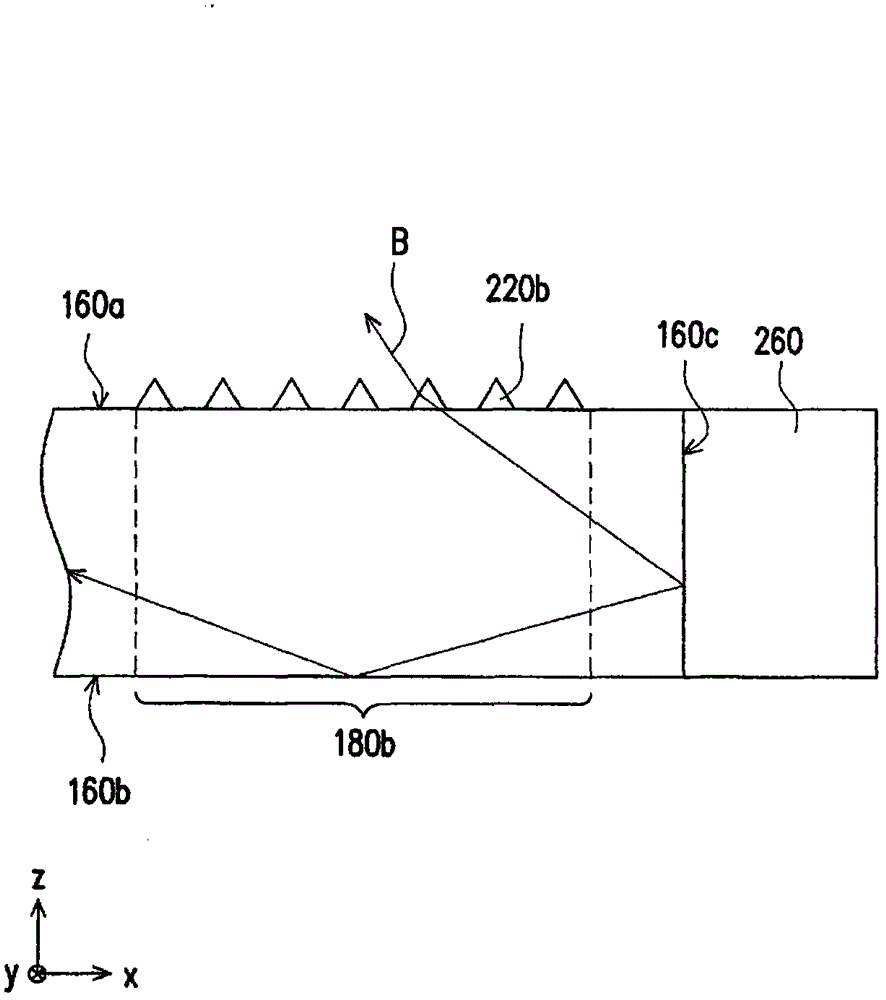
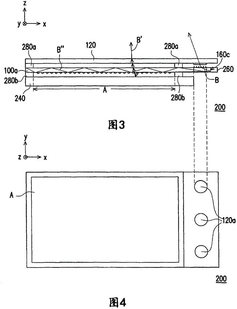
[0046] Figure 1A It is a side view of a display device according to an embodiment of the present invention. see Figure 1A , in this embodiment, the display device 100 includes a display unit 240 , a protective cover 120 , a light guide plate 100 a and a light emitting unit 260 . The display unit 240 has a display area A. As shown in FIG. The protective cover 120 has a pattern area 120a, wherein the pattern area 120a does not overlap with the display area A. As shown in FIG. The light guide plate 100a is disposed between the display unit 240 and the protective cover 120, a...


PUM


Abstract

A display apparatus is provided. A display unit has a display region. A protecting cover has a patterned region, wherein the patterned region does not overlap the display region. A light guide plate is disposed between the display unit and the protecting cover and has a first light scattering region and a second light scattering region. The first light scattering region at least partially overlaps the display region, and the second light scattering region at least partially overlaps the patterned region. A light emitting unit emits a light beam to the light guide plate. After the light beam enters the light guide plate, a part of the light beam is scattered to the display region by the first light scattering region and another part of the light beam is scattered to the patterned region by the second light scattering region.

Description

technical field [0001] The present invention relates to an optical device, in particular to a display device. Background technique [0002] For electrophoretic display panels, liquid crystal display panels and other panels that do not emit light by themselves, they are often matched with light source modules so that the display device can be viewed in an environment with insufficient light. For the transmissive liquid crystal display panel, a backlight module is often used to place behind the transmissive liquid crystal display panel to provide sufficient illumination for the transmissive liquid crystal display panel. On the other hand, for a reflective electrophoretic display panel (such as electronic paper) or a reflective liquid crystal display panel, a front light module is usually arranged in front of the panel, which can also provide sufficient illumination for the panel. [0003] To provide lighting outside the non-display area with the current existing technology, a...

Claims


Application Information

Patent Timeline
Patent Type & Authority Applications(China)
IPC IPC(8): G02F1/13357G02F1/167F21V13/02
CPCG02B6/0093G02B6/0036G02B6/0043G02B6/0058G02B6/006G02B6/0025G02F1/133606G02F1/167
Inventor 陈怡礽戴晟杰许财维施耀淙鲍友南
Owner E INK HLDG INC
Learn More