
Decoding method, memory storage device and memory control circuit unit

A technology of a storage unit and a decoding method, which is applied in the field of decoding, and can solve problems such as uncorrectable low-density parity-check codes, different error correction capabilities of low-density parity-check codes, and non-fixed number of bits, etc.

Active Publication Date: 2015-04-29
PHISON ELECTRONICS
View PDF3 Cites 17 Cited by
  • Summary
  • Abstract
  • Description
  • Claims
  • Application Information

AI Technical Summary

Problems solved by technology

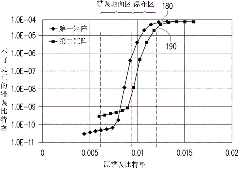
However, the distance between these effective codewords is not fixed, so the number of bits that can be corrected is not fixed
For example, in a codeword (codeword) there are 4 bits in error, and the corresponding low-density parity check code can correct these errors; but in the same codeword, if there are other 3 bits in error , the corresponding LDPC may not be able to correct these errors
In addition, using different sparse matrices, the error correction ability of the LDPC will be different

Method used


Image

  • Decoding method, memory storage device and memory control circuit unit
  • Decoding method, memory storage device and memory control circuit unit
  • Decoding method, memory storage device and memory control circuit unit

Examples


Embodiment Construction

[0102] Generally speaking, a memory storage device (also called a memory storage system) includes a rewritable non-volatile memory module and a controller (also called a control circuit). Typically memory storage devices are used with a host system such that the host system can write data to or read data from the memory storage device.

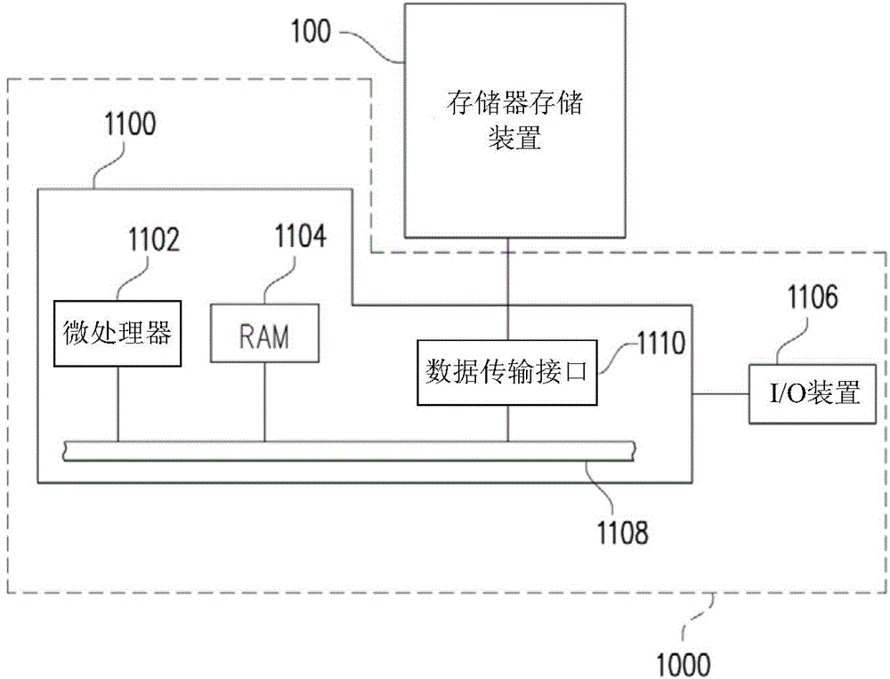
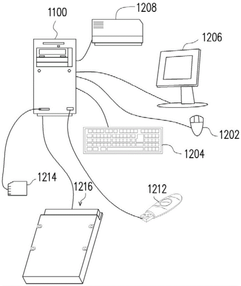
[0103] figure 2 It is a schematic diagram of a host system and a memory storage device provided according to an embodiment of the present invention. image 3 It is a schematic diagram of a computer, an input / output device and a memory storage device according to an embodiment of the present invention.

[0104] Please refer to figure 2 , the host system 1000 generally includes a computer 1100 and an input / output (input / output, I / O for short) device 1106 . The computer 1100 includes a microprocessor 1102 , a random access memory (random access memory, RAM for short) 1104 , a system bus 1108 and a data transmission interface 1110 . The inpu...


PUM


Abstract

The invention provides a decoding method, a memory storage device and a memory control circuit unit. The decoding method comprises the following steps: reading a plurality of storage units according to first reading voltages to obtain a first verification bit; executing a decoding program containing a probability decoding algorithm according to the first verification bit to generate a plurality of first decoding bits, and judging whether decoding succeeds or not by utilizing the first decoding bits; if the decoding fails, reading the storage units according to second reading voltages to obtain a second verification bit; executing the decoding program according to the second verification bit to generate a plurality of second decoding bits, wherein the second reading voltages are different from the first reading voltages, and the number of the second reading voltages is equal to that of the first reading voltages. Thus, the error correcting capacity can be improved.

Description

technical field [0001] The present invention relates to a decoding method, and in particular to a decoding method of a rewritable non-volatile memory module, a memory storage device and a memory control circuit unit. Background technique [0002] Digital cameras, mobile phones, and MP3 players have grown rapidly in recent years, making consumers' demand for storage media also increase rapidly. Since the rewritable non-volatile memory module (for example, flash memory) has the characteristics of data non-volatility, power saving, small size, and no mechanical structure, it is very suitable for being built into the various memory modules listed above. in portable multimedia devices. [0003] Generally, some error correcting code (error correcting code, ECC for short) is added to the data stored in the rewritable non-volatile memory module. In the past, error correction codes mostly used algebraic decoding algorithms, such as (BCH code), but current probabilistic decoding alg...

Claims


Application Information

Patent Timeline
IPC IPC(8): G06F11/10
Inventor 林纬严绍维林玉祥赖国欣郑国义
Owner PHISON ELECTRONICS
Learn More