Capacitor nailing machine discharge device

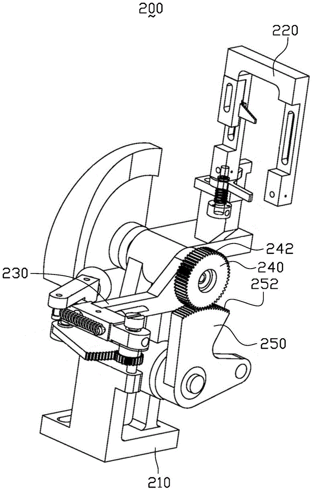
A capacitor and nailing technology, applied in the field of capacitor nailing machine blanking device, can solve the problems of overall structure jitter, difficult installation, and overall structural jitter of the capacitor nailing machine blanking device 200, so as to avoid overall structural jitter, avoid wear effect

Active Publication Date: 2015-04-29
SHENZHEN CHENGJIE INTELLIGENT EQUIP CO LTD
View PDF4 Cites 4 Cited by
  • Summary
  • Abstract
  • Description
  • Claims
  • Application Information

AI Technical Summary

Problems solved by technology

However, the cooperation between the circular driven wheel 240 of the capacitor nailing machine blanking device 200 and the gears 242, 252 of the fan-shaped driving wheel 250 is not easy to install, and a gap is likely to occur between the circular driven wheel 240 and the fan-shaped driving wheel 250, resulting in capacitor nails. The overall structure of the pick-up and unloading device 200 shakes, resulting in unloading of the turning arm 230 or poor connection of needles
In addition, after the circular driven wheel 240 and the fan-shaped driving wheel 250 of the capacitor nailing machine unloading device 200 are meshed for a long time, the tooth surfaces of the gears 242 and 252 of the circular driven wheel 240 and the fan-shaped driving wheel 250 will be worn. Furthermore, there is a gap between the circular driven wheel 240 and the fan-shaped driving wheel 250, which makes the overall structure of the blanking device 200 of the capacitor nailing machine vibrate, and makes the turning arm 230 blank or the needle connection is poor.

Method used


Image

  • Capacitor nailing machine discharge device
  • Capacitor nailing machine discharge device
  • Capacitor nailing machine discharge device

Examples


Embodiment Construction

[0023] Further expounding the technical means and effects that the present invention adopts to achieve the intended purpose of the invention, in conjunction with the accompanying drawings and preferred embodiments, the specific implementation, structure, features and details of the capacitor nailing machine blanking device proposed according to the present invention will be described below. Its efficacy is described in detail as follows.

[0024] The aforementioned and other technical contents, features and effects of the present invention will be clearly presented in the following detailed description of preferred embodiments with reference to the drawings. Through the description of specific implementation methods, the technical means and effects of the present invention to achieve the intended purpose can be understood more deeply and specifically, but the attached drawings are only for reference and description, and are not used to explain the present invention limit.

[...


PUM


Abstract

A capacitor nailing machine discharge device comprises a needle guide and collection mechanism. The needle guide and collection mechanism comprises a machine base and a turning mechanism arranged on the machine base in a rotating mode. The turning mechanism comprises a drive wheel and a turning arm fixed to the drive wheel. The capacitor nailing machine discharge device further comprises a turning drive mechanism and a transmission mechanism. The transmission mechanism comprises a synchronous belt and an elastic assembly connected to one end of the synchronous belt. The turning drive mechanism is connected to the other end of the synchronous belt and drives the synchronous belt to drive the drive wheel, and the turning arm is driven to rotate and reset. Overall structural shaking of the capacitor nailing machine discharge device can be avoided, and the capacitor nailing machine discharge device can normally conduct needle collection and discharge.

Description

technical field [0001] The invention relates to an aluminum electrolytic capacitor nailing machine, in particular to a capacitor nailing machine unloading device. Background technique [0002] figure 1 It is a schematic diagram of a partial three-dimensional structure of an existing capacitor nailing machine blanking device. Such as figure 1 As shown, the existing capacitor nailing machine blanking device 200 includes a machine base 210 , a minute hand support 220 , a turning arm 230 , a circular driven wheel 240 and a fan-shaped driving wheel 250 . The minute hand support 220 is arranged along the vertical direction and connected to the base 210 . The turning arm 230 is arranged along the horizontal direction, and the end of the turning arm 230 is hinged to the base 210 , and the hinged end of the turning arm 230 is located below the minute hand bracket 220 . The circular driven wheel 240 is fixedly connected to the hinged end of the turning arm 230 , and the fan-shaped...

Claims


Application Information

Patent Timeline
Patent Type & Authority Applications(China)
IPC IPC(8): H01G13/00
Inventor 宗勇谭国彪刘云
Owner SHENZHEN CHENGJIE INTELLIGENT EQUIP CO LTD
Why Eureka
Try Eureka