Compact type wafer lifting mechanism

A lifting mechanism, compact technology, applied in the direction of conveyor objects, electrical components, semiconductor/solid device manufacturing, etc., can solve the problems of large space, needle lifting mechanism occupation, etc., to avoid interference, small structural size, save space Effect

Active Publication Date: 2015-04-29
SHENYANG KINGSEMI CO LTD
View PDF11 Cites 8 Cited by
  • Summary
  • Abstract
  • Description
  • Claims
  • Application Information

AI Technical Summary

Problems solved by technology

This vertical arrangement of cylinders makes the needle lift

Method used


Image

  • Compact type wafer lifting mechanism
  • Compact type wafer lifting mechanism
  • Compact type wafer lifting mechanism

Examples


Example Embodiment

[0015] The present invention will be described in further detail below in conjunction with the accompanying drawings.
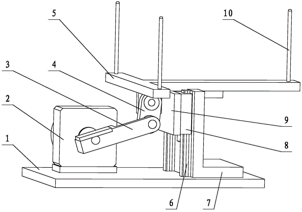
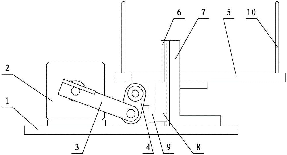
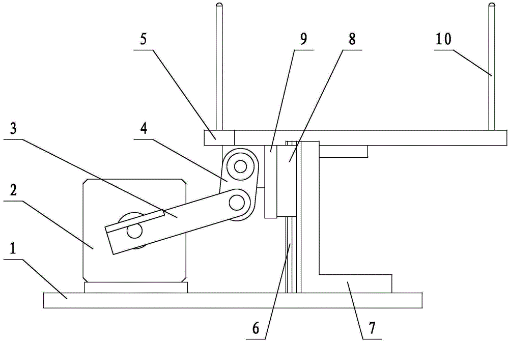
[0016] like figure 1 As shown, the present invention includes a base 1, a swing cylinder 2, a swing rod 3, a connecting rod 4, a needle holder 5 and a guide device that supports and guides the lifting of the needle holder 5, wherein the swing cylinder 2 is fixed on the base 1 The guide device is installed on the base 1 and is located on one side of the swing cylinder 2. One end of the swing rod 3 is fixedly connected with the rotating shaft of the swing cylinder 2, the other end is hinged with one end of the connecting rod 4, and the other end of the connecting rod 4 is hinged with the needle holder 5; One end and the needle holder 5 are hinged. A plurality of film needles 10 are fixed on the film needle frame 5, the swing cylinder 2 drives the swing rod 3 to swing, and the swing rod 3 drives the connecting rod 4, which in turn drives the film needle frame ...


PUM


Abstract

The invention relates to equipment for carrying wafers during the manufacturing of semiconductors, particularly to a compact type wafer lifting mechanism for lifting the wafers when the wafers are taken by mechanical hands. The compact type wafer lifting mechanism comprises a base, a swinging air cylinder, a swinging rod, a connecting rod and a wafer holder carrying the wafers, wherein the swinging air cylinder is mounted on the base, one end of the swinging rod is connected with a rotating shaft of the swinging air cylinder, the other end of the swinging rod is connected with the wafer holder through the connecting rod, the swinging air cylinder drives the swinging rod to swing, and drives the connecting rod through the swinging rod so as to drive the wafer frame carrying the wafers to ascend and descend. According to the invention, the swinging air cylinder drives the swinging rod to rotate so as to drive the wafer holder and the wafers to ascend and descend through the connecting rod. Under the situation of the same wafer lifting distance, compared with the conventional wafer lifting mechanism driven by a straight-rod air cylinder, the compact type wafer lifting mechanism disclosed by the invention has the advantages that the structural size is relatively smaller in the wafer moving direction, the space occupied by the mechanism in the wafer moving direction can be saved, and the mechanism disclosed by the invention is beneficial to structural optimization.

Description

technical field [0001] The invention relates to wafer handling equipment in the semiconductor manufacturing process, in particular to a compact needle lifting mechanism for lifting and lowering the wafer when the wafer is taken and placed by a manipulator. Background technique [0002] Semiconductor manufacturing equipment has high requirements on various aspects such as working environment and working space. During the semiconductor manufacturing process, wafers need to be handled at various stations. The existing needle lifting mechanism for raising and lowering the wafer adopts a linear cylinder, and the telescopic direction of the cylinder rod is consistent with the lifting direction of the needle. This vertical arrangement of cylinders makes the needle lifting mechanism occupy a larger space in the vertical direction. Contents of the invention [0003] In order to meet the requirements of the semiconductor manufacturing equipment on the working space, the object of ...

Claims


Application Information

Patent Timeline
IPC IPC(8): H01L21/677
CPCH01L21/677H01L21/67703
Inventor 门恩国张爽
Owner SHENYANG KINGSEMI CO LTD
Why Eureka
Try Eureka