Battery grouping structure and battery pack comprising same

A group structure and battery pack technology, applied to battery pack parts, batteries, structural parts, etc., can solve problems such as complex production and installation process, no unified support for battery packs, difficult realization of module structure, etc., to achieve suitable mass production Maximize production, achieve consistency requirements, and achieve the effect of fewer parts

Active Publication Date: 2015-04-29
HUBEI JINQUAN NEW MATERIALS CO LTD
View PDF5 Cites 10 Cited by
  • Summary
  • Abstract
  • Description
  • Claims
  • Application Information

AI Technical Summary

Problems solved by technology

For the current series-parallel structure of cylindrical cells used in electric vehicles and large energy storage battery packs, there are mainly the following defects: 1. The battery pack does not have a unified support, the connection between the batteries is disordered and crossed, and the production and installation process and its It is complicated and seriously affects work efficiency; 2. The structure of multi-string modules is difficult to realize; 3. The insulation performance of the modules is not high. For metal casings, insulation boards must be added on all six sides for insulation, which seriously affects the battery. 4. The space utilization rate of the battery module is not high, and the arrangement of the batteries can only be arranged in a matrix, and the space range has not been effectively utilized; 5. The number of fixtures used is large, and the consistency of the entire battery Not strong, battery life does not meet the requirements required by customers

Method used


Image

  • Battery grouping structure and battery pack comprising same
  • Battery grouping structure and battery pack comprising same
  • Battery grouping structure and battery pack comprising same

Examples


Embodiment Construction

[0033] The technical solutions of the present invention will be further described below in conjunction with the accompanying drawings and through specific implementation methods.

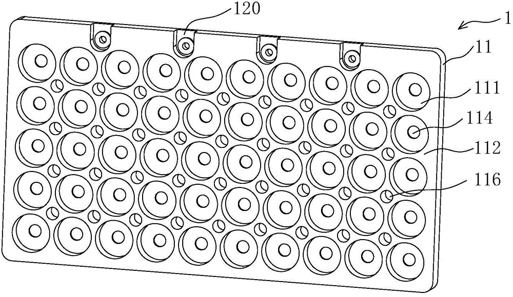
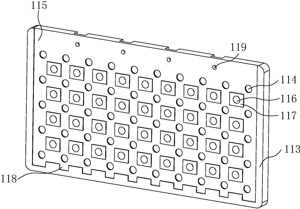
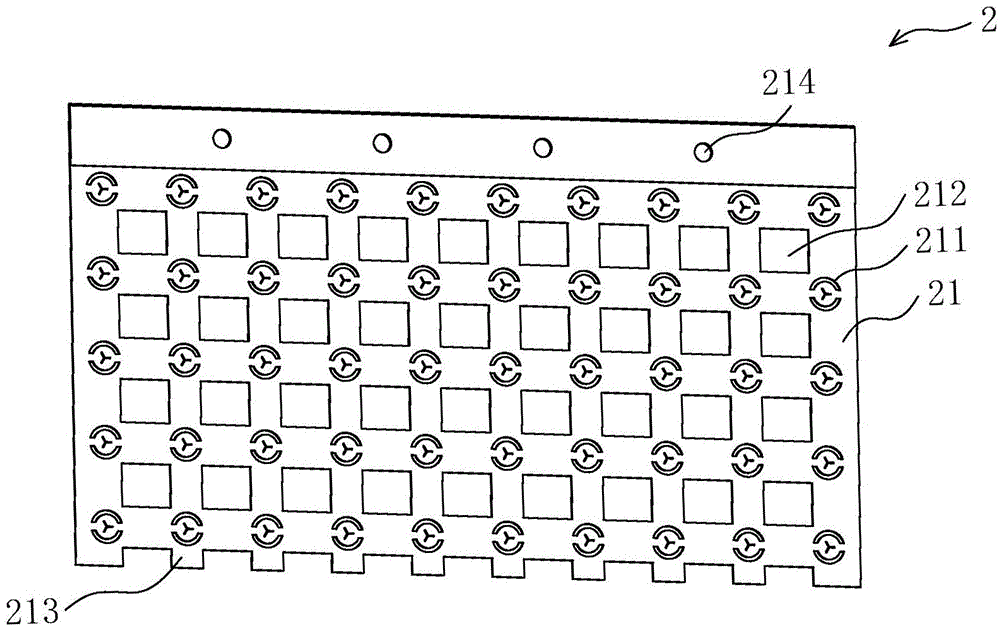
[0034] An embodiment of the present invention provides a battery group structure, including: two fixing plates that can be arranged at both ends of the battery, and an at least partially conductive connecting plate that can be arranged on a side of the fixing plate that is away from the battery; wherein, The fixing plate is provided with a fixing hole for restricting the battery end inside, and the bottom of the fixing hole is provided with a through hole for exposing the battery end to the side of the fixing plate facing away from the battery, The end of the battery can be welded to the connection plate through the through hole, and the connection plate is provided with a limit slot corresponding to the through hole to limit the welding position. The battery group structure uses two fixing plates t...


PUM


Abstract

The invention discloses a battery grouping structure which comprises two fixing plates and a connecting plate, wherein the fixing plates can be arranged at two ends of a battery; the connecting plate can be arranged on one side surface, which deviates from the battery, of the fixing plates; at least one part of the connecting plate is conductive; fixing holes used for limiting the ends of the battery therein are formed in the fixing plates; through holes used for exposing the ends of the battery on one side surface, which deviates from the battery, of the fixing plates are formed in the bottoms of the fixing holes, so that the ends of the battery can penetrate through the through holes and are welded with the connecting plate; and a limiting groove used for limiting the welding position is formed in a position, which corresponds to the through hole, of the connecting plate. According to the battery grouping structure, the battery is clamped between two fixing plates, and a good effect of supporting the battery is achieved; and moreover, the through holes are formed in the bottoms of the fixing holes, so that the ends of the battery are exposed, the battery is fixed with the connecting plate in a welding mode, series-parallel connection among multiple batteries is realized by virtue of the connecting plate, and the grouping structure is fewer in parts, easy to operate and suitable for batch production.

Description

technical field [0001] The invention relates to the technical field of batteries, in particular to a battery pack structure and a battery pack containing it. Background technique [0002] In the prior art, in order to obtain a higher battery capacity, it is necessary to connect multiple single cells in series and parallel to form a group. When the batteries are grouped, it is necessary to ensure the stability of the corresponding electrical connection between the multiple single cells. In the event of a short circuit / open circuit; also ensure the corresponding structural stability. For the current series-parallel structure of cylindrical cells used in electric vehicles and large energy storage battery packs, there are mainly the following defects: 1. The battery pack does not have a unified support, the connection between the batteries is disordered and crossed, and the production and installation process and its It is complicated and seriously affects work efficiency; 2. T...

Claims


Application Information

Patent Timeline
Patent Type & Authority Applications(China)
IPC IPC(8): H01M2/10H01M2/20H01M50/213H01M50/244H01M50/264H01M50/291H01M50/507H01M50/509H01M50/516
CPCH01M2220/20H01M50/20H01M50/50H01M50/572Y02E60/10
Inventor 陈美华程应祥邓锦炽刘智亮李觉
Owner HUBEI JINQUAN NEW MATERIALS CO LTD
Why Eureka
Try Eureka