Electrical connection self-locking terminal

An electrical connection and self-locking technology, which is applied in the direction of conductive connection, connection, electrical components, etc., can solve the problems of wire head connection safety life, reliability difficult to be guaranteed, electrical accidents, line failures, etc., to achieve fast and convenient connection Guaranteed connection quality, safe and reliable use

Active Publication Date: 2017-01-11
中山市沃通电器科技有限公司
View PDF12 Cites 0 Cited by
  • Summary
  • Abstract
  • Description
  • Claims
  • Application Information

AI Technical Summary

Problems solved by technology

[0003] For the connection of the wire ends, the existing technology adopts the method of cross-folding and winding the wire ends, using a variety of tools and accessories. sex is hard to secure
[0004] In addition, in electrical circuit engineering, when the lines pass through different geographical environments, the wire joints will shrink and loosen under the influence of climate cold and heat, and may also be affected by moisture erosion, especially for pipelines that pass through water or buried underground, the wire joints will be damaged. Oxidation, after oxidation, the contact surface will generate resistance, and heat will cause line failure or electrical accident when the current passes
[0005] Since the safety of electricity is paid more and more attention to, there is no good technical solution to solve the above problems

Method used


Image

  • Electrical connection self-locking terminal
  • Electrical connection self-locking terminal
  • Electrical connection self-locking terminal

Examples


Embodiment Construction

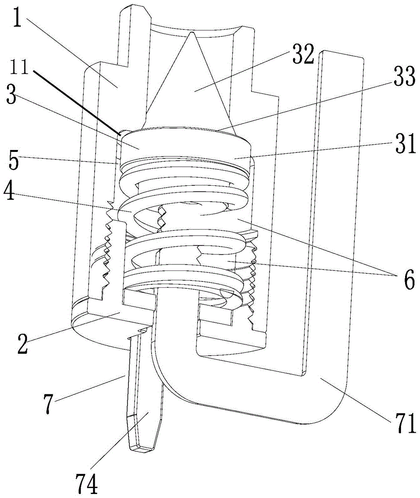
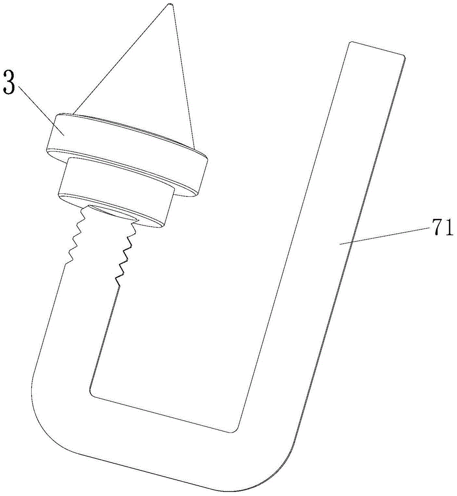
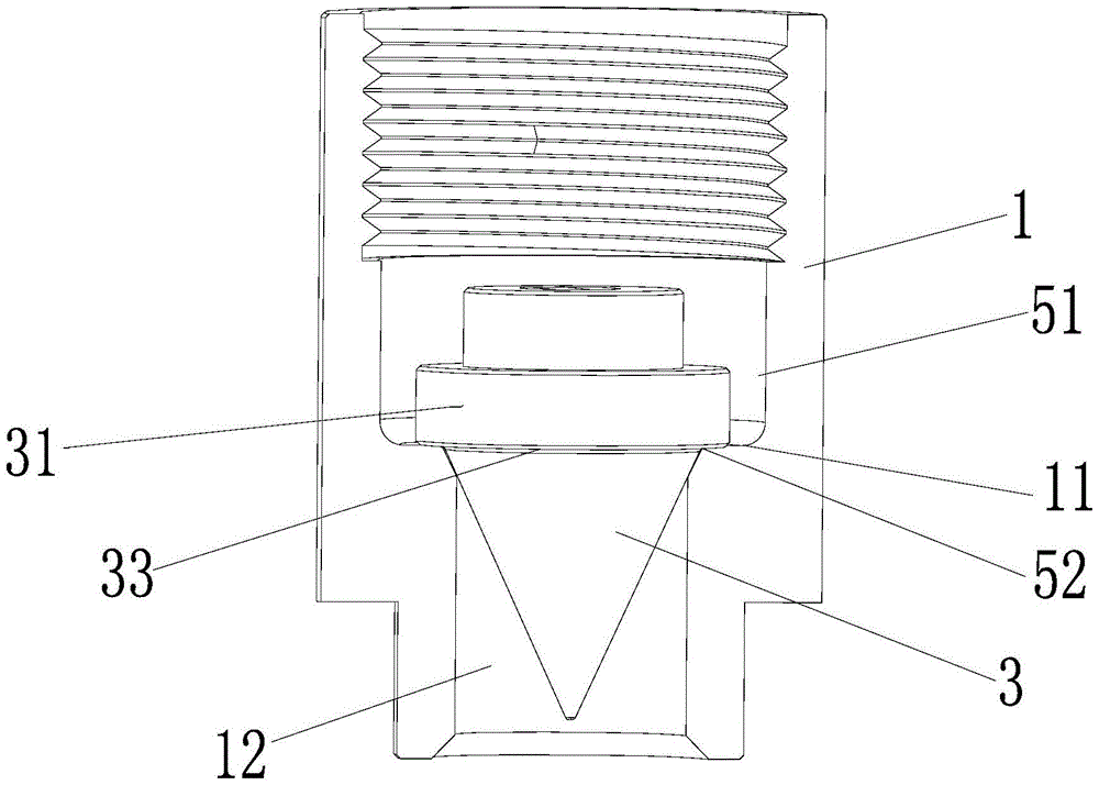
[0031] Figure 1 to Figure 4 , shows an embodiment of the present invention for the connection of electric wires and electrical equipment. The backseat of this mode is a pass structure. It includes the wire inlet seat 1, the guide pressure taper shaft 3 axially installed in the wire inlet seat, the back seat 2 and the spring 4, the wire inlet seat 1 is axially connected with the rear seat 2, and the wire inlet seat 1 and the back seat 2 can be threaded, and can also be integrated. The guide thread taper shaft 3 includes a pressure receiving portion 31 and a branching taper portion 32, a first step 33 is provided between the pressure receiving portion 31 and the branching taper portion 32, and the wire inlet seat 1 has a A second step 11 corresponding to a step 33, there is a gap 5 between the wire inlet seat 1 and the guide crimping cone shaft 3 for the wire to enter, and the wire inlet seat 1 and the rear seat 2 are provided with a mounting In the spring chamber 6 of the s...


PUM


Abstract

The invention discloses an electrical connection self-locking terminal. The electrical connection self-locking terminal comprises a wire inlet hole base, a guide wire pressing conical shaft, a rear base and a spring, wherein the guide wire pressing conical shaft is axially arranged in the wire inlet hole base, the spring is arranged in the rear base, and the wire inlet hole base is axially connected with the rear base. The guide wire pressing conical shaft comprises a pressure bearing portion and a branching conical portion. A gap for wires to enter the electrical connection self-locking terminal is formed between the wire inlet hole base and the guide wire pressing conical shaft. Spring cavities used for installing the spring is formed in the wire inlet hole base and the rear base. One end of the spring abuts against the rear base, and the other end of the spring abuts against the pressure bearing portion of the guide wire pressing conical shaft. The rapid connection and self-locking can be achieved through the connection terminal of the structure, and the electrical connection self-locking terminal is safe, reliable and low in cost.

Description

technical field [0001] The invention relates to an electrical connection device, in particular to an electrical connection self-locking terminal. Background technique [0002] In today's era, electricity is inseparable from people's work and life, and the transmission of electric energy is transmitted to various places in people's work and life through the distribution of power grid lines. Due to the extension of the electric transmission line, the connection of the branch and the forked line end is inevitable, and the connection quality of the wire directly affects the safety, reliability and service life of the electric energy transmission. Line faults often occur in line transmission and cause various electrical accidents, the reasons of which are closely related to the quality of electrical connections. [0003] For the connection of the wire ends, the existing technology adopts the method of cross-folding and winding the wire ends, using a variety of tools and accessor...

Claims


Application Information

Patent Timeline
Patent Type & Authority Patents(China)
IPC IPC(8): H01R13/02H01R13/633H01R4/52H01R31/06
CPCH01R4/5016H01R4/52H01R13/02H01R13/633H01R31/065
Inventor 李树聪
Owner 中山市沃通电器科技有限公司
Why Eureka
Try Eureka