
Flux-switching type parallel hybrid permanent magnet memory motor

A hybrid permanent magnet and memory motor technology, applied in the direction of synchronous machines, electrical components, electromechanical devices, etc., can solve the problems of difficult adjustment of the air gap magnetic field, large iron consumption of the motor, and large loss of weak magnetic flux, etc., to achieve low loss of weak magnetic flux , high motor efficiency and high power density

Active Publication Date: 2015-04-29
SOUTHEAST UNIV
View PDF3 Cites 18 Cited by
  • Summary
  • Abstract
  • Description
  • Claims
  • Application Information

AI Technical Summary

Problems solved by technology

As a permanent magnet motor, the stator permanent magnet motor also has the problem that the air gap magnetic field is difficult to adjust
When the motor is running at low speed, the iron consumption of the motor is large; when the motor is field-weakening for speed regulation, the traditional method uses direct-axis pulse current or a separate field-weakening winding for field-weakening operation. Like other types of permanent magnet motors, there are The problem of large loss in weak magnetic field

Method used


Image

  • Flux-switching type parallel hybrid permanent magnet memory motor
  • Flux-switching type parallel hybrid permanent magnet memory motor
  • Flux-switching type parallel hybrid permanent magnet memory motor

Examples


Embodiment Construction

[0019] The present invention will be further described below in conjunction with the accompanying drawings.

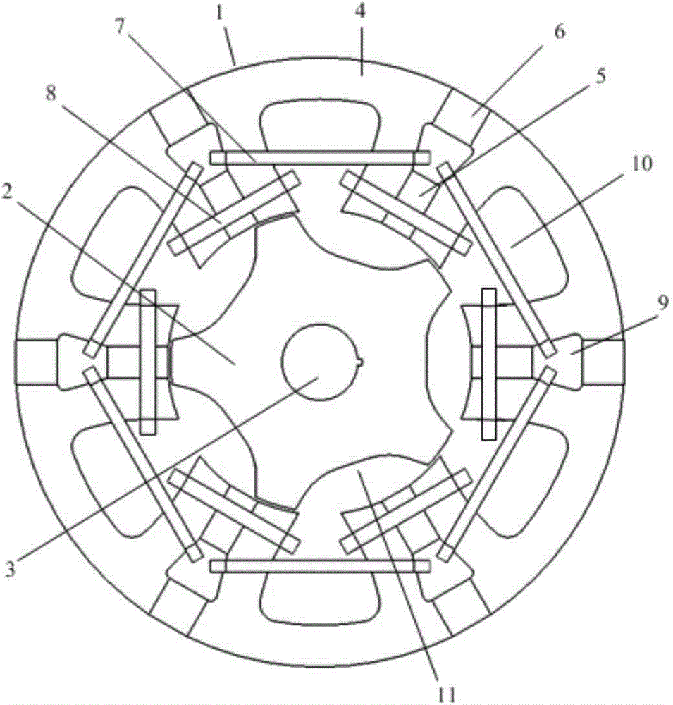
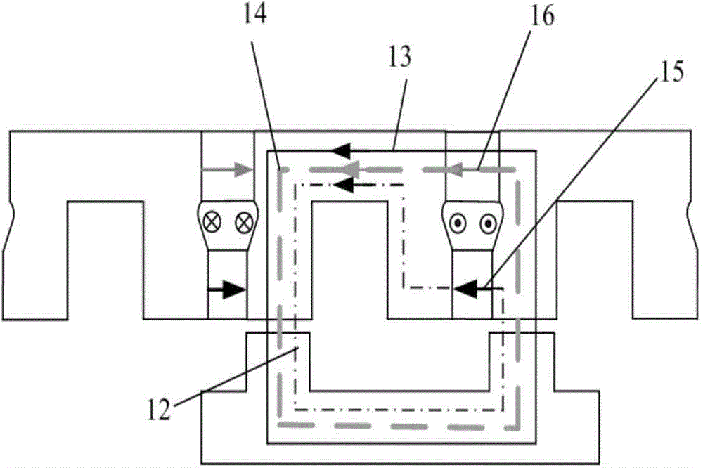
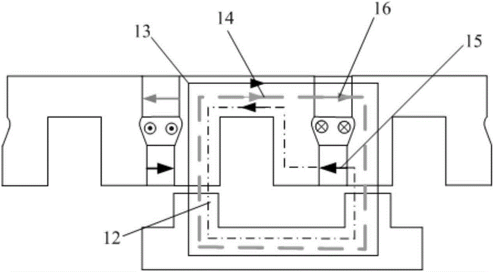
[0020] Such as figure 1 A flux-switching parallel hybrid permanent magnet memory motor shown includes a stator 1, a rotor 2, a non-magnetic rotating shaft 3, and 6n U-shaped stator cores 4, where n is a positive integer; a DC magnetizing coil 7 and an AC concentrated winding The coil 8; the rotor 2 and the stator 1 both adopt a salient pole structure; the rotor 2 is made of laminated silicon steel sheets; the stator 1 is arranged outside the rotor 2, and the rotor 2 is fixed on the nonmagnetic rotating shaft 3.

[0021] The stator 1 includes several U-shaped stator cores 4, all U-shaped stator cores 1 are evenly arranged to form a ring shape, and the openings of the U-shaped stator cores 4 face the rotor; the side ends of the U-shaped stator cores 4 are stator teeth (that is, a U-shaped The stator core 4 has two stator teeth), there is a gap between two adjacent U-sha...


PUM


Abstract

The invention discloses a flux-switching type parallel hybrid permanent magnet memory motor which comprises a stator, a rotor, a non-magnetism-conductive rotating shaft, a plurality of U-shaped stator iron cores, a direct-current magnetizing coil and an alternating-current concentrated winding coil. The U-shaped stator iron cores are evenly distributed to form an annular shape. Stator teeth are arranged at the side ends of the U-shaped stator iron cores. A gap is formed between every two adjacent U-shaped stator iron cores. Each gap and the stator teeth adjacent to the gap form a salient pole. A low-coercivity permanent magnet and a high-coercivity permanent magnet are arranged in each gap in the radial direction, wherein the parallel connection is formed on magnetic circuits of the two permanent magnets, and a direct-current magnetizing coil cavity exists between the two permanent magnets. The direct-current magnetizing coil penetrates through every two adjacent direct-current magnetizing coil cavities to be wound around the U-shaped stator iron cores. The alternating-current concentrated winding coil is wound around the salient poles to form a three-phase armature winding. The magnetization state of the low-coercivity permanent magnets is adjusted by exerting the pulse current in the direct-current magnetizing coil, pulse current is removed, the low-coercivity permanent magnets can be kept in the previous magnetization state, and the variable-flux and memory purposes are achieved.

Description

technical field [0001] The invention relates to a motor, in particular to a magnetic flux switching parallel hybrid permanent magnet memory motor. Background technique [0002] The permanent magnet motor has the characteristics of simple structure, reliable operation, small size, light weight, low loss and high efficiency, so it has a wide range of applications, covering various fields of aerospace, national defense, industry and agriculture, and daily life. With the widespread use of permanent magnet drive motors in household appliances and electric vehicles, the development of low energy consumption permanent magnet drive motors will surely bring significant economic and social benefits. This type of permanent magnet drive motor generally has a small load torque during steady-state operation, and a large load torque when starting. The traditional permanent magnet drive motor design concept is to make the motor more efficient near the rated operating point. However, due to...

Claims


Application Information

Patent Timeline
IPC IPC(8): H02K21/38
Inventor 林明耀李念徐妲郝立付兴贺
Owner SOUTHEAST UNIV
Learn More