Load detection circuit for radio frequency matrix switch
A technology of load detection and matrix switch, which is applied in the direction of electronic switch, logic circuit connection/interface layout, electrical components, etc., can solve the problem that single pole double throw switch is difficult to meet the demand, achieve low return loss and ensure normal output Effect
- Summary
- Abstract
- Description
- Claims
- Application Information
AI Technical Summary
Problems solved by technology
Method used
Image

Examples
Embodiment Construction
[0016] The design will be further described below in conjunction with the accompanying drawings of the description.
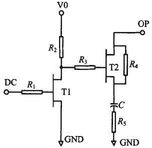
[0017] The radio frequency matrix switch load detection circuit is characterized in that: the load detection circuit is composed of a logic NOT gate and a 50Ω circuit, the transistor T1, the resistor R 1 , resistor R2 forms a logic NOT gate circuit; transistor T2, resistor R3, resistor R4, resistor R5, and capacitor C form a 50Ω circuit.
[0018] further:
[0019] The radio frequency matrix switch load detection circuit is characterized in that: the circuit input voltage terminal Vo provides a normal working voltage.
[0020] The radio frequency matrix switch load detection circuit is characterized in that: when the DC terminal DC is at a high level, the transistor T1 is turned on, and outputs a low level to the gate of T2, and T2 is turned off.
[0021] The radio frequency matrix switch load detection circuit is characterized in that: when the DC is low leve...
PUM
 Abstract
Description
Claims
Application Information