Burst light receiving circuit

A technology of receiving circuit and bias circuit, applied in electromagnetic receivers and other directions, can solve the problems of burst receiving output duty cycle distortion, OLT receiving saturation performance degradation, etc.

Inactive Publication Date: 2015-04-29
APAT OPTOELECTRONICS COMPONENTS
View PDF2 Cites 6 Cited by
  • Summary
  • Abstract
  • Description
  • Claims
  • Application Information

AI Technical Summary

Problems solved by technology

In this burst receiving circuit, when the upstream input ONU / ONT optical signal spectrum is insufficient or missing, it will directly cause the burst receiving output duty cycle of the OLT optical transceiver module to be distorted, and the OLT receiving saturation performance will be degraded

Method used


Image

  • Burst light receiving circuit
  • Burst light receiving circuit

Examples


Embodiment Construction

[0013] The preferred embodiment of the present invention will be described in detail below in conjunction with the accompanying drawings.

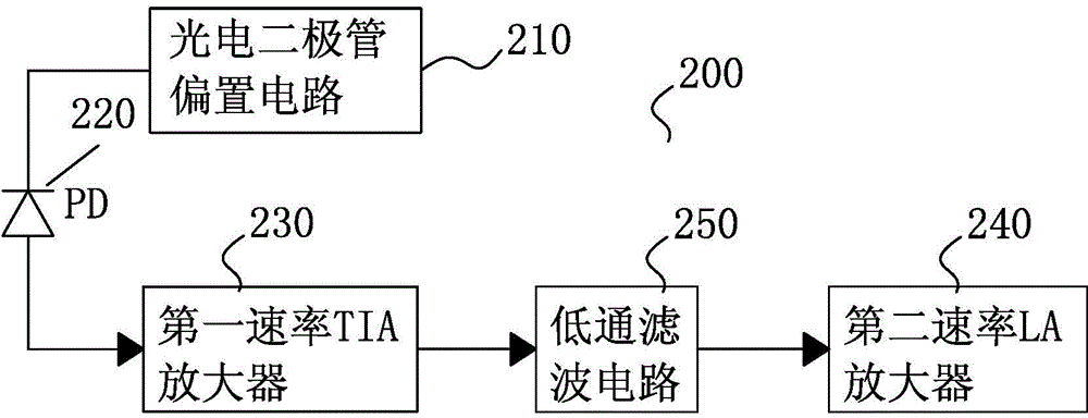
[0014] Such as figure 2 The burst light receiving circuit 200 shown includes: a photodiode bias circuit 210, a photodiode PD220, a first rate TIA amplifier 230, and a second rate LA amplifier 240, the first rate being greater than the second rate , Located between the output terminal of the first rate TIA amplifier 230 and the input terminal of the second rate LA amplifier 240, and further includes a low-pass filter circuit 250. Among them, the photodiode PD220 can be a PIN or APD photodiode. The first rate is 2.5G, and the second rate is 1.25G to match to form a 1.25G burst optical receiver circuit with low spectrum loss; it can also be matched with the first rate of 4G and the second rate to 2.5G to form a spectrum loss Small 2.5G burst light receiving circuit. The low-pass filter circuit 250 is an RC resistor capacitor filter circuit, ...


PUM


Abstract

The invention provides a burst light receiving circuit. The burst light receiving circuit comprises a photodiode biasing circuit, a photodiode, a first-rate TIA (trans-impedance amplifier), a second-rate LA (line amplifier) and a low-pass filter circuit, wherein the first rate is higher than the second rate; the low-pass filter circuit is located between an output end of the first-rate TIA and an input end of the second-rate LA; the first rate is 2.5 G, and the second rate is 1.25 G to be matched with the first rate, so that a 1.25 G burst light receiving circuit with the low frequency spectrum loss is formed; the first rate can also be 4 G, and the second rate is 2.5 G to be matched with the first rate, so that a 2.5 G burst light receiving circuit with the low frequency spectrum loss is formed. The rate of the TIA is higher than that of the LA, and the output end of the high-rate TIA is connected with the low-pass filter circuit, so that the burst receiving bandwidth of an OLT (optical line terminal) optical transceiver module is guaranteed, and the saturation index of a burst light receiving module is improved finally.

Description

Technical field [0001] The invention relates to an optical line terminal OLT optical transceiver module for a passive optical network system, in particular to a burst optical receiving circuit of an OLT optical transceiver module. Background technique [0002] With the development of economic society and communication technology, people's requirements for information and communication are increasing. FTTX optical fiber access technology is a clear direction to increase access speed and expand network capacity. Passive optical network PON (Passive Optical Network, referred to as PON), which has gradually matured in recent years, is a practical solution. The PON network is composed of an optical line terminal OLT (Optical Line Terminal, referred to as OLT) at the central office, an optical network unit ONU (Optical Network Unit, referred to as ONU) on the user side, and ODNs connecting these nodes. The main feature of PON is multi-point (traditional optical network is point-to-poi...

Claims


Application Information

Patent Timeline
Patent Type & Authority Applications(China)
IPC IPC(8): H04B10/69
Inventor 雷岚
Owner APAT OPTOELECTRONICS COMPONENTS
Why Eureka
Try Eureka