Detection method for space modulation signal

A detection method and space modulation technology, which are applied in the direction of preventing/detecting errors through diversity reception, can solve the problems of reduced convergence performance, and achieve the effects of improved convergence and low computational complexity

Active Publication Date: 2015-04-29
HARBIN INST OF TECH
View PDF5 Cites 0 Cited by
  • Summary
  • Abstract
  • Description
  • Claims
  • Application Information

AI Technical Summary

Problems solved by technology

[0005] The purpose of the present invention is to solve the problem that the number of particle types decreases rapidly and the convergence performance decreases as the number of it

Method used


Image

  • Detection method for space modulation signal
  • Detection method for space modulation signal
  • Detection method for space modulation signal

Examples


Example Embodiment

Specific embodiment one:

[0021] The detection method for spatially modulated signals in this embodiment, Particle SwarmOptimization (PSO) was proposed by Dr. Eberhart, an American electrical engineer, and Dr. Kennedy, a social psychologist, in 1995, inspired by bird predation behavior It is an evolutionary computing algorithm that has become the focus of attention of researchers in related fields abroad soon after its publication. The PSO algorithm has the advantages of concise concept, easy implementation and fast convergence speed. In recent years, particle population optimization algorithms have been widely used in many fields such as combinatorial optimization, intelligent computing, and neural networks.

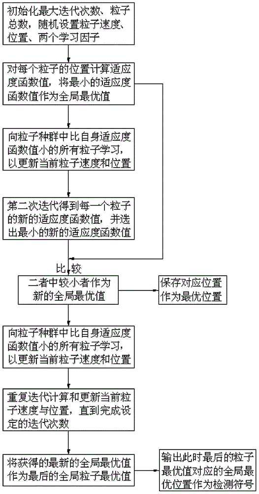
[0022] Such as figure 1 As shown, the detection method is implemented through the following steps:

[0023] Step 1. In D-dimensional space, take the potential solution of the signal to be detected as a particle, and all potential solutions form a particle population. Set th...

Example Embodiment

Specific implementation manner two:

[0029] The difference from the first embodiment is that in the detection method for spatial modulation signals of this embodiment, the current particle velocity of each particle is updated in step 3 By formula: V id k + 1 = ω V id k + c 1 * ( P gd k - X id k ) + c 2 * X n = 1 m ω nd ( P nd k - X id k ) Learn from all particles in the population that are smaller than the fitness function value q of the current particle position to get the updated speed Where

[0030] Represents the current particle velocity,

[0031] Indicates the gap between the global optimal position and the current position, c 1 It is a randomly generated number between 0 and 4, usually the value is 2;

[0032] Represents learning from all particles in the population that are smaller than the fitness function value q of the current particle position accordin...

Example Embodiment

Specific implementation manner three:

[0040] The difference from the first or second embodiment is that in the detection method for spatial modulation signals of this embodiment, the current particle velocity is The learning degree of all particles in the population that is smaller than the fitness function value q of the current particle position is determined by the weight function ω nj Decided.


PUM


Abstract

The invention provides a detection method for a space modulation signal, and belongs to the field of antenna transmission. The traditional particle swarm optimization has problems that the particle species number is quickly reduced and the convergence performance is reduced along with the increasing of iteration times in a space modulation signal detection procedure. The detection method for the space modulation signal comprises the following steps: during each iteration, mapping the position of each particle to a space according to space modulation characteristics, calculating a fitness function value capable of reflecting good or bad performances of the particles; comparing the fitness function value of a current particle with a self optimal fitness function value of a history particle, wherein the minimum value is utilized as a newest global optimal value; updating positions and speeds of the particles by learning an optimal particle of a particle swarm and learning all the particles with the relatively good performances in the particle swarm; and after iteration calculation reaches the maximum time, outputting a global optimal position corresponding to a final global optimal value as a detection symbol, namely the detection symbol corresponding to a receiving symbol.

Description

technical field [0001] The invention relates to a detection method for space modulation signals. Background technique [0002] Spatial modulation is a new type of multi-antenna transmission technology. Different from traditional two-dimensional (real number domain, imaginary number domain) modulation technology, spatial modulation introduces the third dimension: the spatial dimension, which uses the serial number of the transmitting antenna as a new mapping resource. Through The mapping relationship between different input bits and antenna serial numbers is established to achieve the purpose of spatial modulation. In traditional multi-antenna technology, whether it is multiplexing or diversity, all symbol information is sent through all transmitting antennas, while in spatial modulation, some information is implicit in the selection of antennas and is not actually transmitted. The receiving end restores the serial number of the antenna that sends the information through a c...

Claims


Application Information

Patent Timeline
IPC IPC(8): H04L1/06
CPCH04L1/06
Inventor 管春萌刘宁庆张文彬韩雪刘通
Owner HARBIN INST OF TECH
Why Eureka
Try Eureka