
Automatic rail transit illumination control system

An automatic control system and rail transit technology, applied in the field of transportation, can solve the problems of distracting train drivers, low energy saving efficiency, and inability to meet passenger comfort requirements, etc., to facilitate data statistics and records, and realize intelligence and energy saving, to achieve the effect of large-capacity storage

Inactive Publication Date: 2015-04-29
吉林瑞电科技有限公司
View PDF2 Cites 4 Cited by
  • Summary
  • Abstract
  • Description
  • Claims
  • Application Information

AI Technical Summary

Problems solved by technology

[0003] The disadvantages of this operation are as follows: (1) Frequent shutdown and start-up of fluorescent lamps will increase the wear and tear of fluorescent lamp tubes and shorten their lifespan severely
(2) Pressing the light switch button frequently will greatly increase the workload of the train driver, and it is easy to distract the train driver's attention during driving, which may cause accidents
(3) This control method is too subjective and cannot meet the comfort requirements of passengers, and the energy saving efficiency is not high
Obviously, this lighting control method can no longer meet the needs of energy saving, comfort and intelligence in railway traffic.

Method used


Image

  • Automatic rail transit illumination control system
  • Automatic rail transit illumination control system

Examples


Embodiment Construction

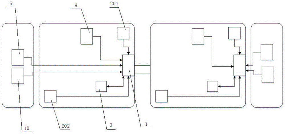
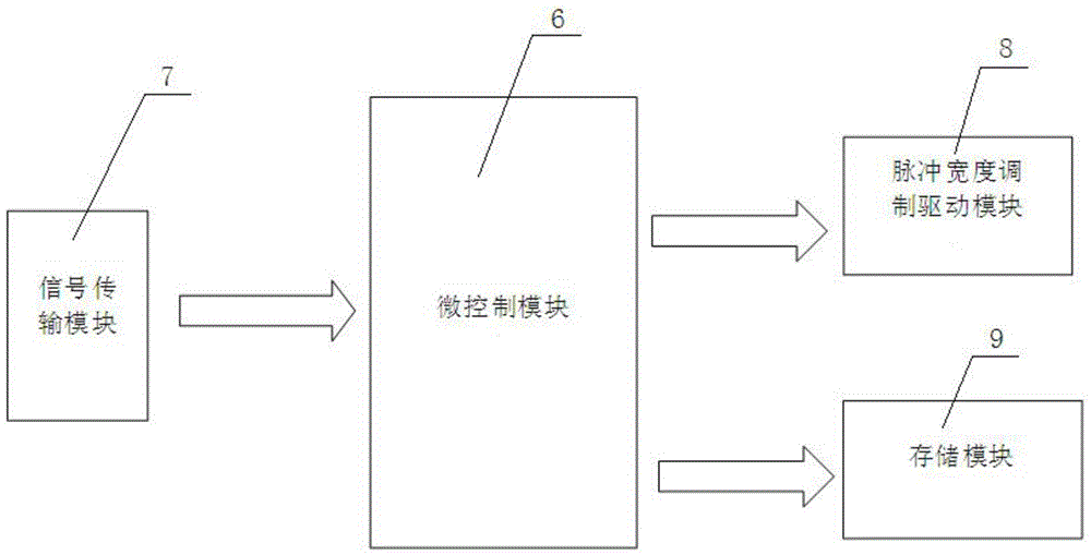
[0019] A rail transit lighting automatic control system, as shown in the figure, includes a main controller 1, a light intensity acquisition module 2, a control system power supply module 4, a mode selection switch group 5 and an input module 10, the inside of the main controller 1 The circuit board is provided with a micro-control module 6, a signal transmission module 7, a pulse width modulation drive module 8 and a storage module 9, and the light intensity acquisition module 2 and the micro-control module 6 arranged inside the main controller 1 pass through the signal transmission module 7 connection; the output end of the micro-control module 6 is connected with the storage module 9 data, and is connected with the signal input end of the pulse width modulation drive module 8; the signal output end of the pulse width modulation drive module 8 is arranged in the compartment The LED lighting lamp 3 is connected; the mode selection switch group 5 includes an automatic mode swit...


PUM


Abstract

The invention discloses an automatic rail transit illumination control system, and belongs to the technical field of transportation. The automatic rail transit illumination control system comprises master controllers, light intensity acquisition modules, control system power supply modules, mode selection switch groups and input modules. Micro-control modules, signal transmission modules, pulse width modulation driving modules and storage modules are arranged on internal circuit boards of the master controllers, the light intensity acquisition modules are connected with the micro-control modules by the signal transmission modules, and the micro-control modules are arranged inside the master controllers; output ends of the micro-control modules are in data connection with the storage modules and are connected with signal input ends of the pulse width modulation driving modules; signal output ends of the pulse width modulation driving modules are connected with LED illuminating lamps which are arranged in carriages; output ends of the input modules are connected with the micro-control modules inside the master controllers. The automatic rail transit illumination control system has the advantages of intelligence and energy conservation of illumination control modes for the insides of the rail carriages and capabilities of improving the riding comfort of passengers and relieving workload on train staffs.

Description

technical field [0001] The invention belongs to the technical field of transportation, in particular to a rail transit lighting system. Background technique [0002] At present, the existing rail transit lighting control systems all adopt human control, and the train staff judges the brightness in the compartment and determines the opening and closing of the lighting lamps. This lighting control method cannot respond to real-time brightness changes in time, so that the lights are often in a long-term running state or cannot be turned on in time, resulting in waste of energy and reducing the comfort of passengers. The unscientific energy-saving method of the lighting system in the train compartment causes the loss of the lighting equipment in the train to increase, and the service life of the equipment is seriously shortened. For the consideration of saving electric energy, the interior lights of rail transit vehicles are artificially controlled, that is, when the weather is...

Claims


Application Information

Patent Timeline
Patent Type & Authority Applications(China)
IPC IPC(8): H05B37/02
Inventor 王保华
Owner 吉林瑞电科技有限公司
Learn More