
Gear flowmeter

A flowmeter and gear technology, applied in the field of gear flowmeters, can solve the problems of high starting torque, influence, and inaccurate measurement, and achieve the effect of reducing starting torque

Inactive Publication Date: 2015-04-29
KEM KUEPPERS ELEKTROMECH
View PDF5 Cites 0 Cited by
  • Summary
  • Abstract
  • Description
  • Claims
  • Application Information

AI Technical Summary

Problems solved by technology

These leaked flows have a detrimental effect on the accuracy of cross-flow determinations
In addition, the friction between the rotations of the measuring gears not only leads to inaccurate measurements, but also to high starting torques, which is to be prevented in the measurement of the lower fluid flow

Method used


Image

  • Gear flowmeter
  • Gear flowmeter
  • Gear flowmeter

Examples


Embodiment Construction

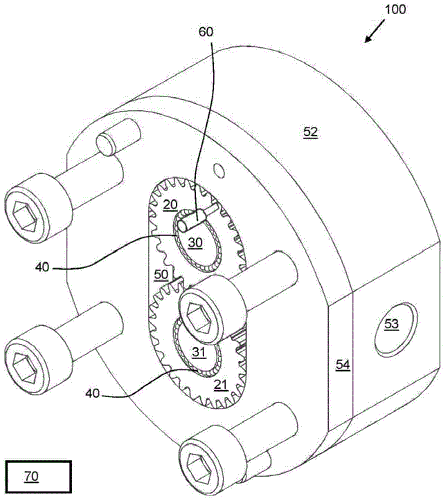
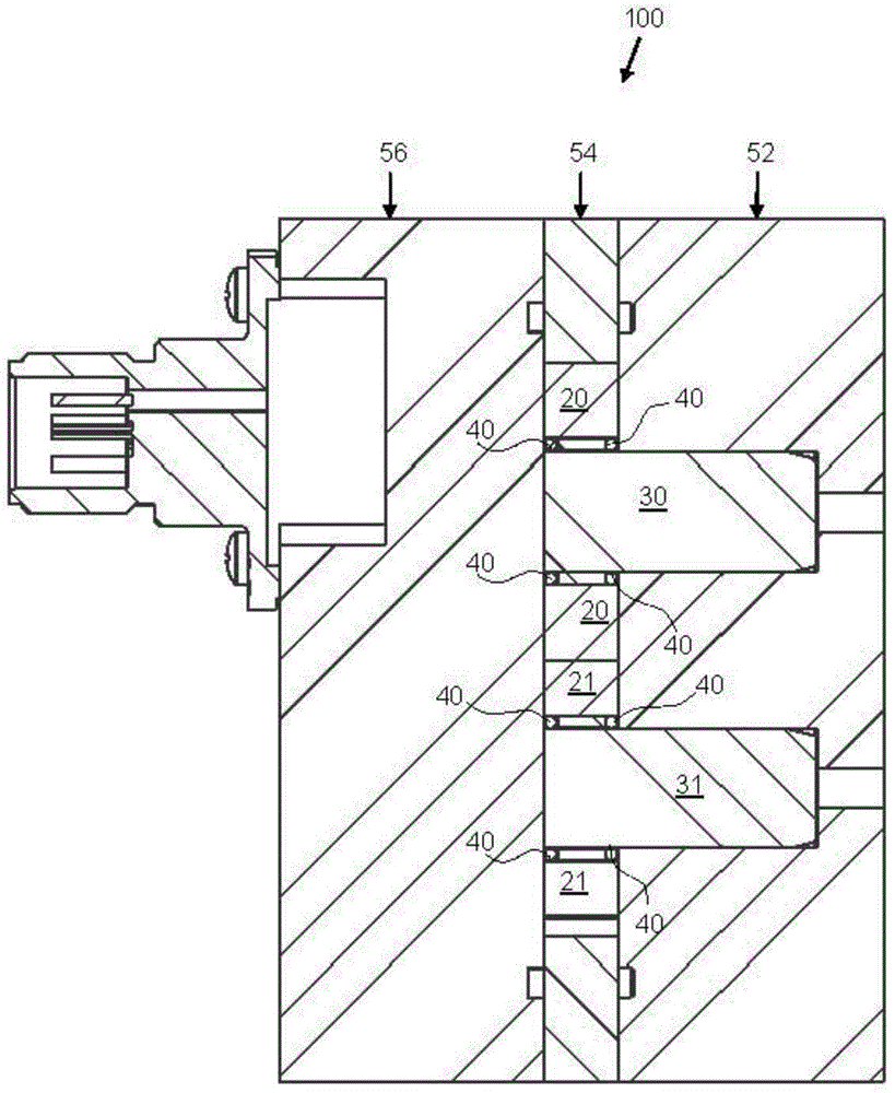
[0057] In accordance with the present invention, an exemplary embodiment of a gear flow meter 100 initially refers to figure 1 with figure 2 describe. figure 1 Then a perspective view of the gear flowmeter 100 is shown, figure 2 A sectional view thereof is then shown, which extends along the axis of rotation of the gear flowmeter 100 .

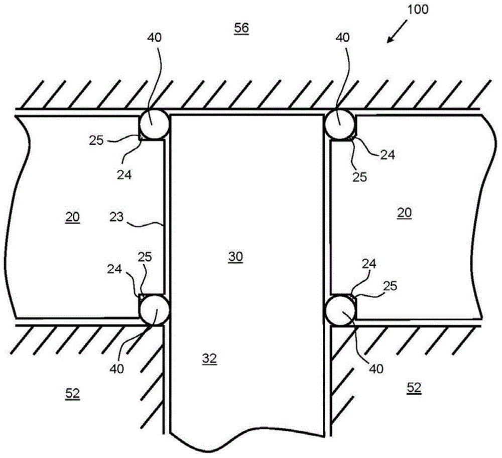
[0058] As necessary components, the gear flowmeter 100 has a gear chamber 50, two measuring gears 20 and 21 disposed therein, respective rotating shafts 30 and 31 of the two measuring gears 20 and 21 and rolling elements for mounting the measuring gears 20 and 21. Element 40.

[0059] In principle, a single measuring gear 20 is also sufficient, or there are more than two measuring gears.

[0060] Preferably, the fluid can only traverse the gear chamber 50 between adjacent teeth of one of the measuring gears 20, 21 on the walls of the gear chamber. Through this flow, the fluid can set the measuring gears 20, 21 in motion. As soon as t...


PUM


Abstract

The gear flowmeter (100) has a gear chamber (50) in which measuring gears (20,21) are arranged. An evaluation unit (70) is provided for determining a flow rate of the fluid through the gear chamber based on gear rotation. The rolling elements (40) for bearing the measuring gears are provided in the receiving area formed between the measuring gear and the bottom (52) and between the measuring gear and the cover. The rolling elements are directly contacted to and movable relative to the measuring gear, the rotational shafts (30,31) and the bottom or cover.

Description

technical field [0001] The invention relates to a gear flow meter as claimed in claim 1 above. Background technique [0002] Gear meters can in principle be used to measure any fluid flow. For example, the fluid may be paint, adhesives, ethanol, solvents, additives, microdosed chemicals, gasoline or diesel. It is thus possible, in particular, to verify injection in the case of diesel engines. [0003] A common gear flow meter for measuring fluid flow has a gear chamber in which at least one measuring gear is arranged, the gear chamber has a bottom and a cover, the gear chamber is divided into the end face of the at least one measuring gear, wherein for each A measuring gear is centrally provided with a respective axis of rotation, wherein each measuring gear is mounted rotatably and fluid is transferable through the gear chamber to rotate at least one measuring gear. In addition, such gear flow meters have a measuring unit to detect the gear rotation and an evaluation dev...

Claims


Application Information

Patent Timeline
Patent Type & Authority Applications(China)
IPC IPC(8): G01F3/10F16C33/58
CPCF16C19/18F16C33/581G01F3/10
Inventor 于尔根·弗里施哈拉尔德·比林托马斯·施托伊尔
Owner KEM KUEPPERS ELEKTROMECH
Learn More