
Whole vehicle functional safety monitoring system

A functional safety and monitoring system technology, applied in the field of automotive safety, can solve the problems of system complexity and system cost increase, high cost, insufficient to meet the functional safety design, etc., to reduce the requirements of functional safety level, reduce complexity and cost , Improve the effect of error detection mechanism

Active Publication Date: 2015-05-06
UNITED AUTOMOTIVE ELECTRONICS SYST
View PDF4 Cites 25 Cited by
  • Summary
  • Abstract
  • Description
  • Claims
  • Application Information

AI Technical Summary

Problems solved by technology

[0010] In this related technology, a distributed torque monitoring structure is still used in the torque monitoring structure. The vehicle acceleration information used in the vehicle state monitoring function only comes from the vehicle speed signal, and there is no redundant verification signal to calibrate the acceleration information. Therefore, centralized vehicle status monitoring cannot be realized, so the functional safety level of the whole vehicle has not been effectively degraded and allocated, resulting in a significant increase in system complexity and system cost
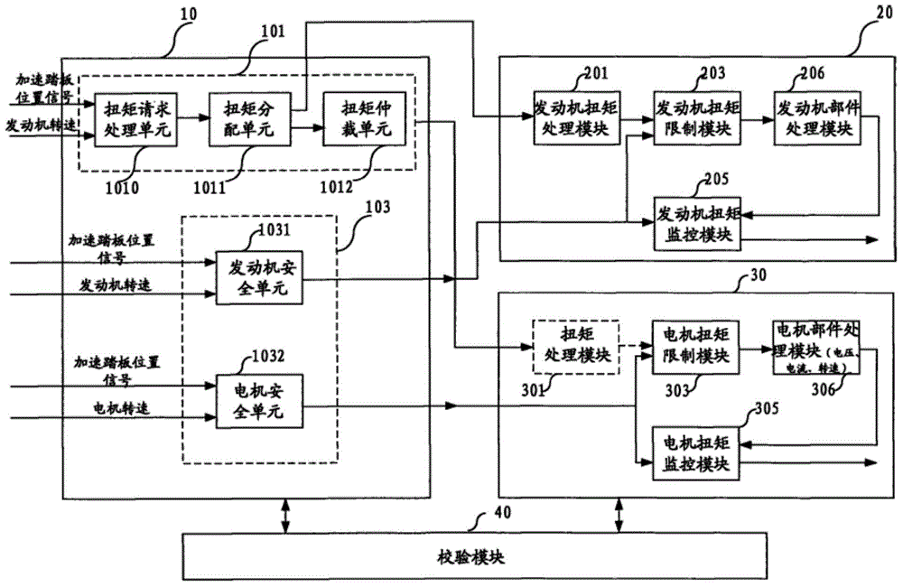
[0011] It can be seen from the above that the existing vehicle functional safety monitoring system adopts a distributed functional safety monitoring structure based on torque distribution. Based on the requirements of the ISO 26262 standard, the distributed functional safety monitoring system usually adopts the following Figure 5 The topological structure of the functional safety level shown is complex and costly; the existing vehicle functional safety monitoring system adopts a similarity redundant functional safety software architecture design, which is not enough to meet more Functional safety design with high functional safety level

Method used


Image

  • Whole vehicle functional safety monitoring system
  • Whole vehicle functional safety monitoring system
  • Whole vehicle functional safety monitoring system

Examples


Embodiment 1

[0045] Vehicle functional safety monitoring system, such as Figure 7 As shown, it includes an acceleration signal source and a main control module 11;

[0046] The acceleration signal source is used to output the instantaneous acceleration of the vehicle to the main control module 11;

[0047] The main control module 11 includes a power control module 111, a safe torque monitoring module 112, and a safe acceleration monitoring module 113;

[0048] The power control module 111 is used to calculate the driver's wheel-end demand torque of the vehicle power system, decompose the driver's wheel-end demand torque of the vehicle power system into engine demand torque and motor demand torque, and distribute the engine demand torque to The engine electronic controller distributes the required torque of the motor to the motor controller, and controls the drive chain clutch to work; if the functional safety fault response of the safety acceleration monitoring module 113 is received or ...

Embodiment 2

[0060] Based on the first embodiment, the vehicle functional safety monitoring system further includes a monitoring module 12;

[0061] The monitoring module 12 communicates with the main control module 11, and monitors whether the power control module 111, the safety torque monitoring module 112, and the safety acceleration monitoring module 113 are normal. If the power control module 111, the safety torque monitoring module 112 Or the safe acceleration monitoring module 113 is not running normally or the main control module 11 has a hardware failure, triggering the reset of the main control module 11 .

[0062] In the vehicle functional safety monitoring system of Embodiment 2, the monitoring module 12 is a hardware monitoring layer, which is mainly responsible for monitoring the main control module 11, preventing logical or temporal failure of the main control module from causing torque calculation errors and causing abnormalities in the vehicle. Expected Accelerated Risk. ...

Embodiment 3

[0064] Based on the vehicle functional safety monitoring system of Embodiment 1, the safety acceleration monitoring module 113 calculates and diagnoses the actual vehicle instantaneous acceleration according to the vehicle instantaneous acceleration information transmitted from the acceleration signal source and the vehicle speed signal;

[0065]If the deviation between the instantaneous acceleration calculated based on the vehicle instantaneous acceleration information transmitted from the acceleration signal source and the instantaneous acceleration calculated based on the vehicle speed signal is within a certain threshold range, it is determined that the acceleration detection information is valid, and the actual instantaneous acceleration of the vehicle under the current working condition is determined. acceleration;

[0066] If the instantaneous acceleration calculated based on the vehicle instantaneous acceleration information transmitted from the acceleration signal sour...


PUM


Abstract

The invention discloses a whole vehicle functional safety monitoring system, which is a centralized whole vehicle functional safety monitoring system with a torque monitoring and an acceleration monitoring, an acceleration signal source is introduced for monitoring the instantaneous whole vehicle acceleration information in real time, the validity of the whole vehicle torque distribution control is considered by the torque comparison monitoring and the whole vehicle acceleration comparison monitoring, when the whole vehicle power system torque calculation and controlling occur an undesired torque increase, security protection can be carried out on the basis of the torque comparison information and the whole vehicle acceleration information of the current vehicle, so that the centralized monitoring of the vehicle functional safety can be realized; the whole vehicle functional safety monitoring system has the advantage that the requirement on the function safety level of the terminal power source controller is lowered, so that the complexity and cost of the monitoring system is reduced, and realization of the systematic design with the more higher functional security level is facilitated.

Description

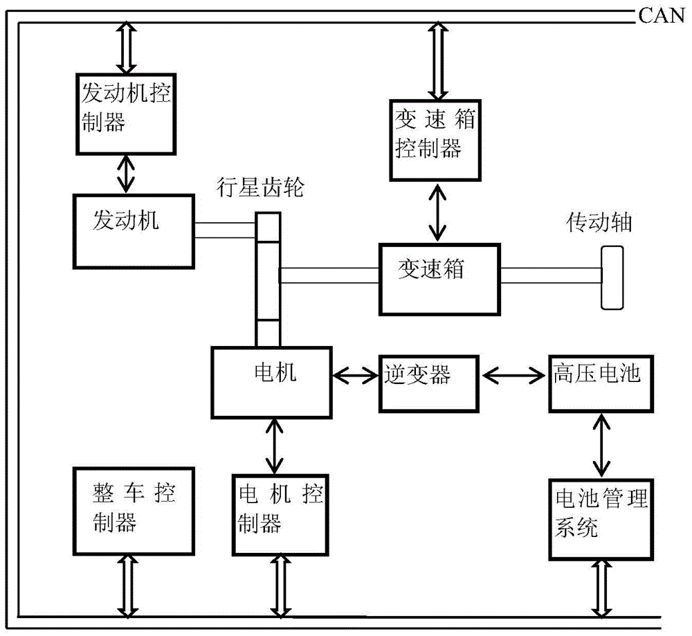
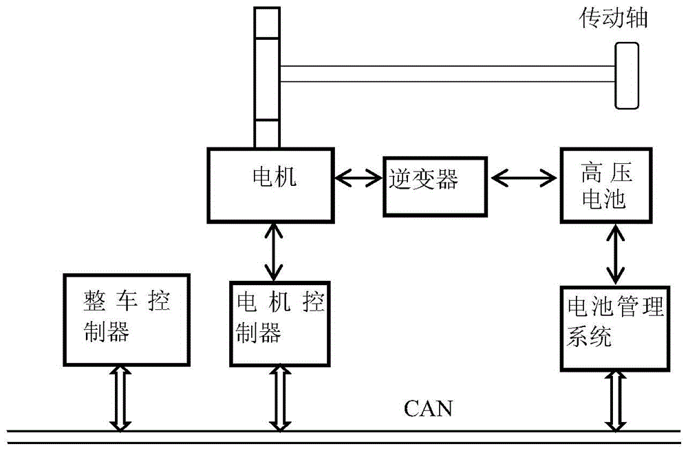
technical field [0001] The invention relates to automobile safety technology, in particular to a vehicle function safety monitoring system. Background technique [0002] With the development of automobile energy saving and emission reduction technology, the automobile power control system has become increasingly complex, and has expanded from the traditional single power control system to the vehicle multi-power control system (such as hybrid power system and electric vehicle control system), figure 1 and figure 2 The structure diagrams of the whole vehicle power control system of hybrid electric vehicle and pure electric vehicle are respectively shown by figure 1 , figure 2 It can be seen that the power system control of the vehicle is controlled by the vehicle controller, engine controller, motor controller and battery management system. The core of the vehicle power system has been transferred from the traditional engine electronic controller to the vehicle controller...

Claims


Application Information

Patent Timeline
IPC IPC(8): B60W10/06B60W10/08B60W10/02B60W40/105B60W40/107B60W50/038
CPCB60W10/02B60W10/06B60W10/08B60W40/107B60W50/038B60W2520/105B60W2710/021B60W2710/0666B60W2710/083
Inventor 于世涛郭辉张威蒋云李君
Owner UNITED AUTOMOTIVE ELECTRONICS SYST
Learn More