Check patentability & draft patents in minutes with Patsnap Eureka AI!

Simple outlet sluice structure with waterproof rubber strip

A technology of waterproof rubber strips and drainage gates, which is applied in water conservancy projects, artificial waterways, sea area projects, etc., can solve the problems of gate leakage, item damage, restoration and cleaning, etc., to reduce sediment deposition, prolong service life, and improve gate structure simple effect

Inactive Publication Date: 2015-05-06
WUPING HONGXIN IND TECH DEV
View PDF0 Cites 0 Cited by
  • Summary
  • Abstract
  • Description
  • Claims
  • Application Information

AI Technical Summary

Problems solved by technology

[0002] Drainage sluice is a very important throttling and flood discharge equipment in water conservancy projects, especially for rainy areas. People living in low-lying areas and coastal areas always worry about flooding, because once flooding occurs, the garbage carried in the water will It is not only difficult to restore and clean up in the future, but also time-consuming and labor-intensive, and it may also cause damage to items.
Existing gates generally used for water-stopping are usually made of cast iron materials, which have simple structure, good water-stopping performance, and long service life. The connection of the gate is prone to water leakage, and the water-stop effect is not good. Under the condition of high water pressure, it cannot withstand high water pressure. In severe cases, damage accidents will occur, and it is difficult to guarantee its own safe operation in emergencies.

Method used


Image

  • Simple outlet sluice structure with waterproof rubber strip

Examples


Embodiment Construction

[0019] The present invention is described in further detail now in conjunction with accompanying drawing. These drawings are all simplified schematic diagrams, which only illustrate the basic structure of the present invention in a schematic manner, so they only show the configurations related to the present invention.

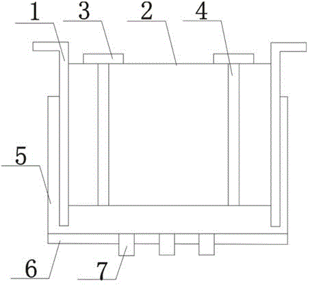
[0020] Such as figure 1 The preferred embodiment of the simple drainage gate structure with waterproof rubber strips shown in the present invention includes a gate 1, the gate 1 is an inverted L-shaped structure, and there are two gates 1, and a gate is installed between the two gates 1 2. The gate 2 and the gate 1 are connected by a rotating shaft. There is a side baffle 5 on the outside of the gate 1. The side baffle 5 and the gate 1 are fixedly connected. The side baffle 5 is composed of two vertical baffles. It is composed of a horizontal baffle, and the vertical baffle is integrally connected with the horizontal baffle. The lower surface of the horizonta...


PUM


Abstract

The invention discloses a simple outlet sluice structure with a waterproof rubber strip. The simple outlet sluice structure comprises two flashboards, the flashboards are of reversed-L-shaped structures, a sluice gate is arranged between the two flashboards, the sluice gate is connected with the flashboards through rotating shafts, lateral blocking plates are arranged on the outer sides of the flashboards, and the lateral blocking plates are fixedly connected with the flashboards. The lateral blocking plates are each composed of two vertical blocking plate bodies and a horizontal blocking plate body, and the vertical blocking plate bodies are integrally connected with the horizontal blocking plate body. Overflowing plates are arranged on the lower surfaces of the horizontal blocking plate bodies, filling valve devices are arranged between the overflowing plates and the horizontal blocking plate bodies, the filling valve devices are mechanically connected with the overflowing plates and the horizontal blocking plate bodies, the number of the filling valve devices is larger than one, and the filling valve devices are evenly arranged between the horizontal blocking plate bodies and the overflowing plates. An adjusting bolt is arranged on the upper surface of the sluice gate. The outlet sluice structure with the waterproof rubber strip is simple in structure, convenient to operate and not prone to being damaged. The outlet sluice structure is effectively protected, the service life of the outlet sluice structure is prolonged, and water can flow through the outlet sluice structure better.

Description

technical field [0001] The invention relates to a water conservancy construction structure, in particular to a simple drainage gate structure with waterproof adhesive strips. Background technique [0002] Drainage sluice is a very important throttling and flood discharge equipment in water conservancy projects, especially for rainy areas. People living in low-lying areas and coastal areas always worry about flooding, because once flooding occurs, the garbage carried in the water will It is not only difficult to restore and clean up in the future, but also time-consuming and labor-intensive, and it may also cause damage to the items. Existing gates generally used for water-stopping are usually made of cast iron materials, which have simple structure, good water-stopping performance, and long service life. The connection of the gate is prone to water leakage, the water-stop effect is not good, and under the condition of high water pressure, it cannot withstand high water pres...

Claims


Application Information

Patent Timeline
IPC IPC(8): E02B7/20E02B5/08
CPCE02B7/40E02B5/08E02B7/54
Inventor 钟强
Owner WUPING HONGXIN IND TECH DEV
Features
  • R&D
  • Intellectual Property
  • Life Sciences
  • Materials
  • Tech Scout
  • Unparalleled Data Quality
  • Higher Quality Content
  • 60% Fewer Hallucinations
Learn More