Cable Gripper

A cable clip and cable technology, which is applied to pipe supports, mechanical equipment, pipes, etc., can solve the problems of easy falling off of cables, inability to put in grooves, time-consuming and laborious loading and unloading operations, etc., so as to avoid operation accidents and cable damage, loading and unloading operations. Simple and fast, simple and fast effect

Active Publication Date: 2019-04-05
HUAIBEI SHENZHENG ELECTRIC POWER ELECTRIC CONTROLEQUIP
View PDF8 Cites 0 Cited by
  • Summary
  • Abstract
  • Description
  • Claims
  • Application Information

AI Technical Summary

Problems solved by technology

[0004] (1) Special tools such as wrenches must be used for loading and unloading cables; tools such as wrenches of appropriate specifications must be used to open bolts and disassemble cables; loading and unloading operations are time-consuming and laborious;
[0005] (3) The compression of the cable is fastened by the bolt, which is controlled by the staff based on hand feel and experience, making it difficult to grasp the compression of the cable, and it is easy to cause the cable to be too tight or too loose; too tight will easily damage the cable, and too loose The cable is easy to fall off;
[0006] (4) In addition, during disassembly and assembly, if the removed parts such as the pressure plate, bolts and nuts are not carefully preserved, the pressure plate, nuts and other bulk components are easily damaged or lost; especially there are many cable clamps in the distribution box When holding, splints, nuts, and bolts of different specifications are scattered and easily lost;
[0007] (5) Since the size of the groove of the bent plate is specific, it must be matched with the cable of the corresponding specification; if the cable is too thin, the cable cannot be fixed; if the cable is too thick, it cannot be placed in the groove; The versatility is relatively poor, and it is difficult to adapt to various cables or wires with different diameters and cross-sectional shapes on site
It is generally used for temporary clamping of multiple cables during electrical tests, and cannot adapt to complex cable types and external strong dragging at industrial maintenance sites.
[0010] The above two patents do not break away from the structural model of the cable splint, and they also have the same disadvantages of the cable splint.

Method used


Image

  • Cable Gripper
  • Cable Gripper
  • Cable Gripper

Examples


Embodiment Construction

[0034] Hereinafter, the present invention will be further described through specific embodiments in conjunction with the accompanying drawings.

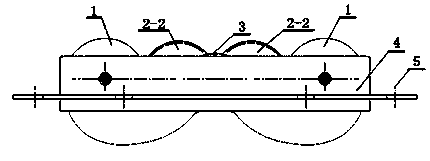
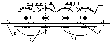
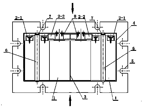
[0035] See Figure 1 ~ Figure 5 , The cable clamp of the present invention includes a frame, a mounting plate 4, and two symmetrically arranged clamping bodies arranged on the mounting plate 4, and the clamped cable 12 is clamped to the two clamping bodies Between; the clamping body includes two cams 1, a torsion spring 7, four synchronization gears; the cable 12 is clamped between the two cams 1 and in contact with the two cams 1, the cam 1 The contour line of the clamping side that is in contact with the supported cable 12 is an involute; the cam 1, torsion spring 7, and synchronization gear are all mounted on the mounting plate 4; the torsion spring 7 is used to enable the cam 1 to rotate Automatically reset, and enable the cam 1 to clamp the clamped cable 12; the synchronization gear includes two driving synchronization gears 2-1 a...


PUM


Abstract

The invention discloses a cable clamping device. The cable clamping device comprises a framework, an installation plate and two clamping bodies which are symmetrically arranged on the installation plate, wherein each clamping body comprises two cams, a torsion spring and four synchronous gears; a clamped cable is clamped between the two cams and contacts with the two cams, and a contour line of a clamping side, contacting with the clamped cable, of each cam is an evolvent; the cams, the torsion spring and the synchronous gears are arranged on a mounting plate; the torsion spring enables the cams to be automatically reset after rotation and enables the cams to clamp the clamped cable; the synchronous gears include two driving synchronous gears and two driven synchronous gears; the two driving synchronous gears rotate synchronously together with cam clamping blocks. The cable clamping device has advantages that various flat and circular cables in a given specification range can be clamped, the cable can be disassembled without a wrench, the operation is simple and rapid, the universality is good, the use is convenient and rapid and the like.

Description

Technical field [0001] The invention relates to a cable clamp. Background technique [0002] A large number of various maintenance power boxes and temporary power distribution boxes (cabinet) are installed on the industrial site, which are mainly used for temporary electricity use such as electric welding machines, motor test runs, construction lighting, and power tools. How to quickly and reliably fix (and disassemble) temporary power distribution cables so that when the cable is dragged and pulled by external forces, the conductive core wire and the terminal end are not directly stressed, so as to avoid breaking the core wire, loosening the connector, and poor contact , Short-circuit grounding, insulation damage, personal electric shock and other faults are common problems faced in the field wiring of mobile power distribution devices such as power boxes. [0003] At present, the conventional fixing method for temporary cables of this type of distribution box is to use a cable c...

Claims


Application Information

Patent Timeline
Patent Type & Authority Patents(China)
IPC IPC(8): F16L3/00
CPCF16L3/02F16L3/04F16L5/00
Inventor 王淮生刘宏伟马良伟李威
Owner HUAIBEI SHENZHENG ELECTRIC POWER ELECTRIC CONTROLEQUIP
Why Eureka
Try Eureka