Device and method for detecting cross-rod distance of broaches

A detection device, a technology of spanning bar distance, applied in the field of mechanical processing, can solve the problems of large application limitation, spanning bar distance measurement error, reduction of processing efficiency, etc. and efficiency effects

Active Publication Date: 2019-11-05
JIANGSU GAOJING MECHANICAL & ELECTRICAL EQUIPMENT CO LTD
View PDF4 Cites 0 Cited by
  • Summary
  • Abstract
  • Description
  • Claims
  • Application Information

AI Technical Summary

Problems solved by technology

[0004] In the prior art, measuring rods are usually used to measure the cross-rod distance of involute spline broaches, but in the traditional process of cross-rod distance measurement, it is often carried by hand or fixed by plasticine, instead of using The jig used to fix the measuring rod between the blades of the broach; the form of human hand holding is instantaneous and unstable, and it is often difficult to grasp the best position of the measuring rod, resulting in large errors in the measurement of the distance between the rods. However, the plasticine fixed form is easy to change the position of the measuring rod due to the deformation of the plasticine, resulting in measurement errors, and this form is very difficult to operate without disassembling the broach, which affects the measurement of the cross-rod distance efficiency; in addition, in the process of measuring the traditional cross-rod distance, because most of the inspection tools are mechanical structures, there are often certain reading errors and poor stability, and the U-shaped structure after reading needs to be manually input into the numerical control system, and then Control the grinding wheel for grinding, which leads to a further reduction in processing efficiency, and in order to improve processing efficiency and accuracy, it is often necessary to measure the broach without disassembling it on the machine tool, which is necessary for most cross-bar distance detection in the prior art. It is difficult to implement the tools. Although there have been CNC machine tools with automatic measurement of electric probes, they are often expensive and have relatively limited applications.

Method used


Image

  • Device and method for detecting cross-rod distance of broaches
  • Device and method for detecting cross-rod distance of broaches
  • Device and method for detecting cross-rod distance of broaches

Examples


Embodiment Construction

[0035] In order to make the object, technical solution and advantages of the present invention clearer, the present invention will be further described in detail below in conjunction with the accompanying drawings and embodiments. It should be understood that the specific embodiments described here are only used to explain the present invention, not to limit the present invention.

[0036] In addition, the technical features involved in the various embodiments of the present invention described below can be combined with each other as long as they do not constitute a conflict with each other.

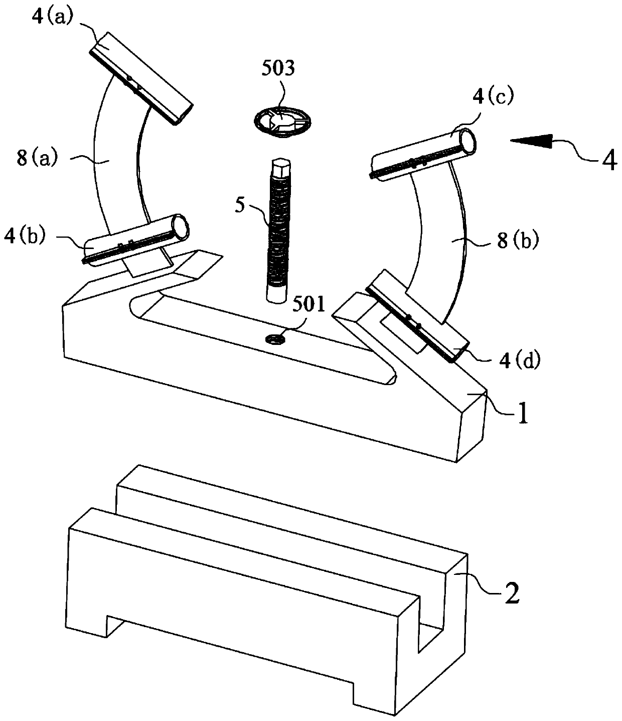
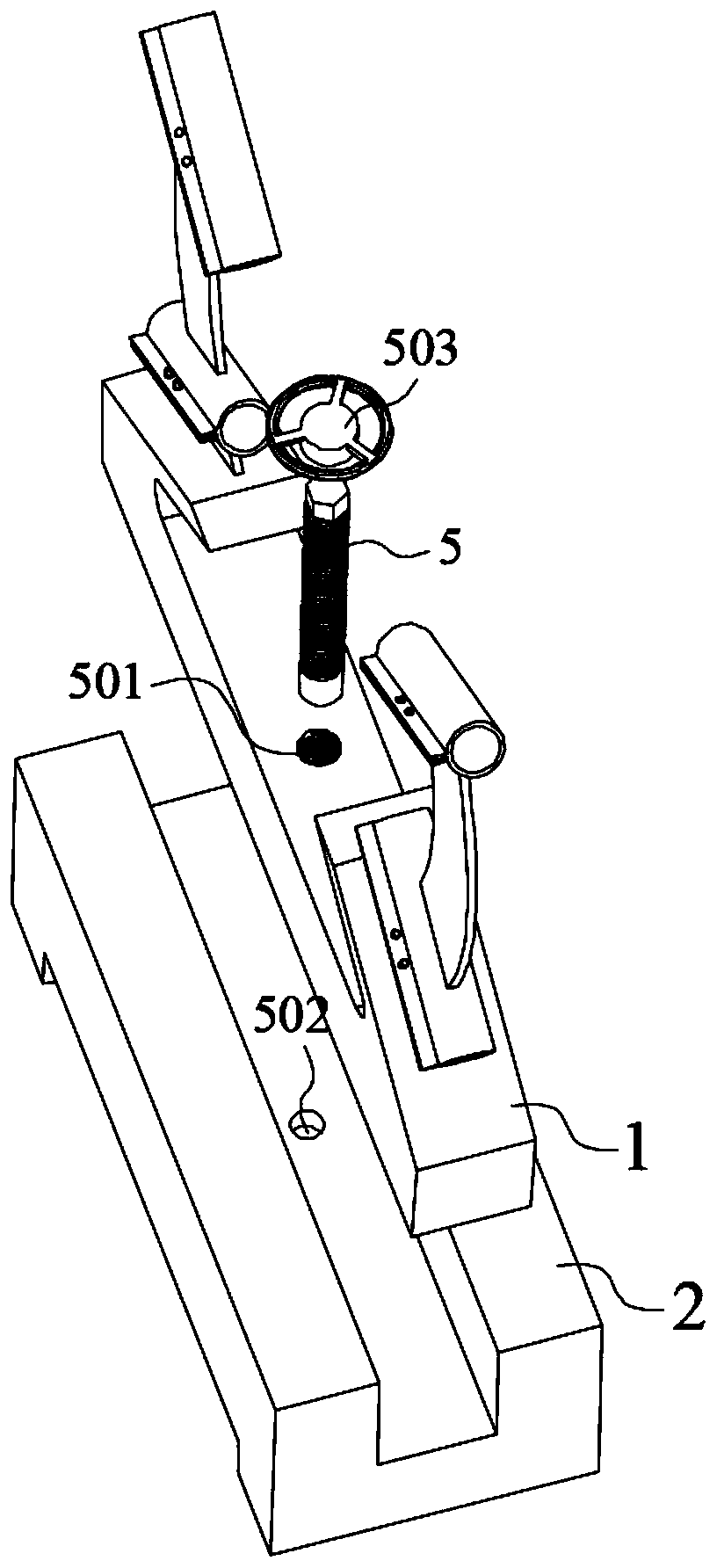
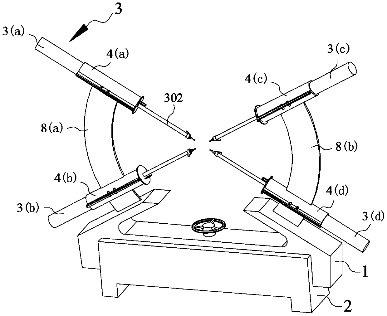
[0037] In the preferred embodiment of the present invention, the overall structure of the bar-crossing detection device of the broach is as follows: figure 1 with figure 2 As shown in , it preferably includes a support frame 1 and a mobile platform 2. A plurality of sleeves 4 that can accommodate displacement sensors 3 are arranged on the support frame 1, and a corresponding number of...


PUM


Abstract

The invention discloses a detection device and a detection method for a broach bar distance, which belong to the field of mechanical processing. Set up a pair of sleeves that are distributed at corresponding intervals in the vertical direction. By optimizing the positions of the four sleeves and assembling and fixing two sets of displacement sensors correspondingly, the two sets of displacement sensors can complete the broach crossing through the process of zero calibration and detection. distance detection. In the detection device and detection method for the distance across the broach of the broach according to the present invention, the detection device has a simple structure, is convenient to assemble, the steps of the detection method are simple and convenient, and has strong operability. Improve the efficiency of cross-rod detection, reduce the error of cross-rod detection, reduce the economic cost of cross-rod detection, and have excellent application and promotion value.

Description

technical field [0001] The invention belongs to the field of mechanical processing, and in particular relates to a detection device and a detection method for a cross-rod distance of a broach. Background technique [0002] With the continuous development of machining technology, new requirements are put forward for the efficiency and precision of machining. In the field of mechanical processing, a broach is a forming tool used for broaching. There are usually multiple rows of cutter teeth on the outer peripheral surface of the cutter, and the size and shape of each row of cutter teeth often increase sequentially from the cutting end to the cutting end. And changes, and then when the broach is broaching, each tooth cuts a certain thickness of material from the workpiece, and finally obtains the required size and shape. The broach is often used in batch or mass production to process round holes, Spline hole, keyway or for machining planes, etc. [0003] Spline hole processin...

Claims


Application Information

Patent Timeline
Patent Type & Authority Patents(China)
IPC IPC(8): G01B7/14
CPCG01B7/14
Inventor 喻道远徐秀兵朱碧华郑金来陈满意丁玲张猛崔海斌李玉萍周伯华张超勇龚时华朱海平邓超肖华军黄平韬
Owner JIANGSU GAOJING MECHANICAL & ELECTRICAL EQUIPMENT CO LTD
Why Eureka
Try Eureka