Automatic argon blowing connector device

A joint device and automatic technology, applied in the direction of pipes/pipe joints/fittings, adjustable connections, passing components, etc., can solve the problem that the male end of the joint is not easy to disassemble and replace, so as to save replacement and installation time, improve production efficiency, and reduce replacement effect of difficulty

Active Publication Date: 2015-05-06
WUXI JULI HEAVY IND OFF
View PDF6 Cites 5 Cited by
  • Summary
  • Abstract
  • Description
  • Claims
  • Application Information

AI Technical Summary

Problems solved by technology

[0003] In view of the above problems, the present invention provides an automatic argon-blowing joint device, which can effectively solve the problem that the male end of the existing automatic argon-blowing joint is not easy to disassemble and replace after being worn out,

Method used


Image

  • Automatic argon blowing connector device
  • Automatic argon blowing connector device
  • Automatic argon blowing connector device

Examples


Embodiment Construction

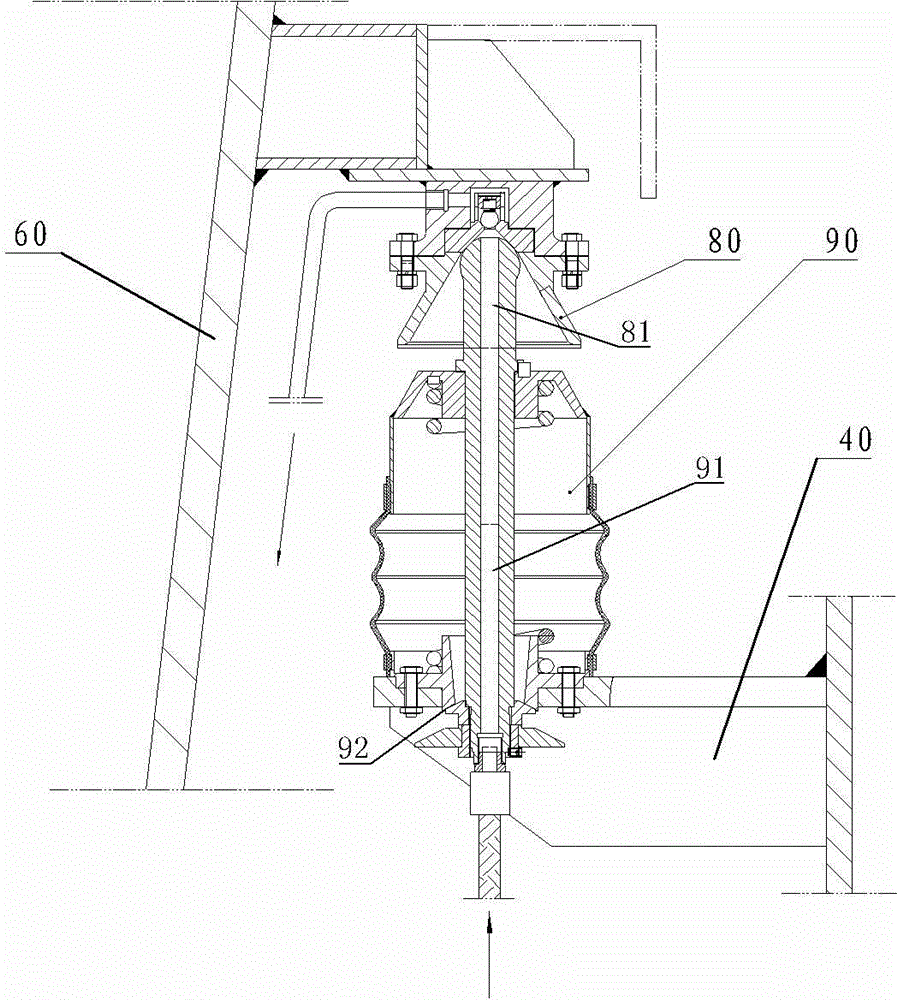
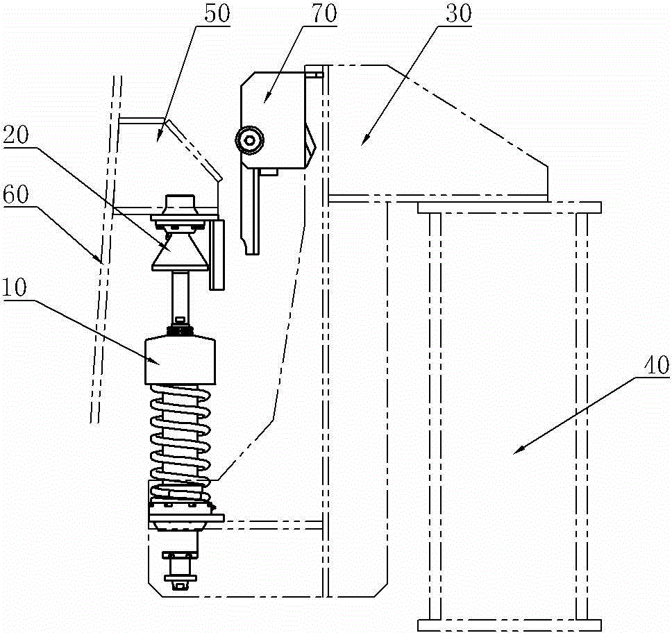
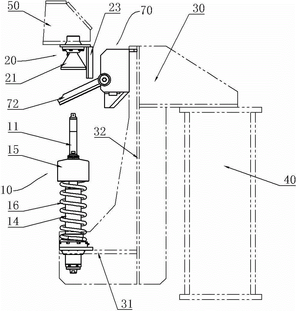
[0028] See figure 2 and image 3 , the automatic argon blowing joint device of the present invention includes a joint male end 10 and a joint female end 20, the joint male end 10 is fixedly installed on the transfer device 40 through the male end mounting frame 30, and the joint female end 20 is installed on the On the tank wall 60 of the steel ladle; see Figure 4 , the male end of the joint 10 includes a male end joint body 11, and the male end joint body 11 is provided with an axially penetrated air duct 12, and the male end joint body 11 includes a coaxial detachable top joint body 111, a joint main body 112, and a bottom The joint body 113, the two ends of the joint body 112 are respectively detachably connected with the top joint body 111 and the bottom joint body 112, and the top joint body 111, the joint main body 112, and the bottom joint body 113 are respectively provided with ventilation pipes 121, 122, 123, And the vent pipes 121, 122, 123 of the top joint body,...


PUM


Abstract

The invention provides an automatic argon blowing connector device. The problem that after being worn, a connector male end of an existing automatic argon blowing connector is not easily detached to be replaced can be effectively solved. The device comprises a connector male end and a connector female end, wherein the connector male end is fixedly arranged on transfer equipment through a male end mounting frame; the connector female end is arranged on the tank wall of a molten steel tank through a female end mounting frame; the connector male end comprises a male end connector body; a ventilating pipeline which is axially through is formed in the male end connector body. The device is characterized in that the male end connector body comprises a top part connector body, a connector main body and a bottom part connector body which are coaxially and detachably connected into a whole; two ends of the connector main body are detachably connected with the top part connector body and the bottom part connector body, respectively; a ventilating pipeline is respectively formed in each of the top part connector body, the connector main body and the bottom part connector body; the ventilating pipelines of the top part connector body, the connector main body and the bottom part connector body are coaxially through.

Description

technical field [0001] The invention relates to the field of auxiliary equipment in the steelmaking production process, in particular to an automatic argon blowing joint device. Background technique [0002] During the molten steel transfer process under the furnace, the molten steel tank needs to blow argon to the molten steel to achieve the effect of stirring the molten steel. Generally, argon blowing devices are usually installed on the transfer equipment under the furnace, such as molten steel tank cars and ladle turrets. When the molten steel When the tank is dropped, it is necessary to connect the argon pipeline of the molten steel tank with the argon blowing device on the transfer equipment. At present, most of the docking operations are performed manually through quick-change joints. Due to the heat dissipation of the molten steel during transfer It will cause the precipitation of sulfur and phosphorus in the molten steel, resulting in the splashing of molten steel a...

Claims


Application Information

Patent Timeline
IPC IPC(8): F16L27/053C21C7/072
CPCC21C7/072F16L27/053
Inventor 赵洪柱王凤良
Owner WUXI JULI HEAVY IND OFF
Why Eureka
Try Eureka