Direct current to direct current conversion circuit

A technology of DC conversion and circuit, which is applied in the direction of DC power input conversion to DC power output, output power conversion device, AC power input conversion to DC power output, etc., and can solve the problem that the DC-DC conversion scheme cannot be applied to a wide range of changes Issues such as input and output voltage scenarios to achieve the effect of ensuring conversion efficiency

Active Publication Date: 2015-05-06
XIAN RUIXIN TECH CO LTD
View PDF6 Cites 6 Cited by
  • Summary
  • Abstract
  • Description
  • Claims
  • Application Information

AI Technical Summary

Problems solved by technology

[0004] The present invention provides a DC-DC conversion circuit, which is used to solve the problem that the exi

Method used


Image

  • Direct current to direct current conversion circuit
  • Direct current to direct current conversion circuit
  • Direct current to direct current conversion circuit

Examples


Example Embodiment

[0023] In order to make the objectives, technical solutions, and advantages of the embodiments of the present invention clearer, the technical solutions in the embodiments of the present invention will be described clearly and completely in conjunction with the accompanying drawings in the embodiments of the present invention. Obviously, the described embodiments It is a part of the embodiments of the present invention, not all the embodiments. Based on the embodiments of the present invention, all other embodiments obtained by those of ordinary skill in the art without creative work shall fall within the protection scope of the present invention.
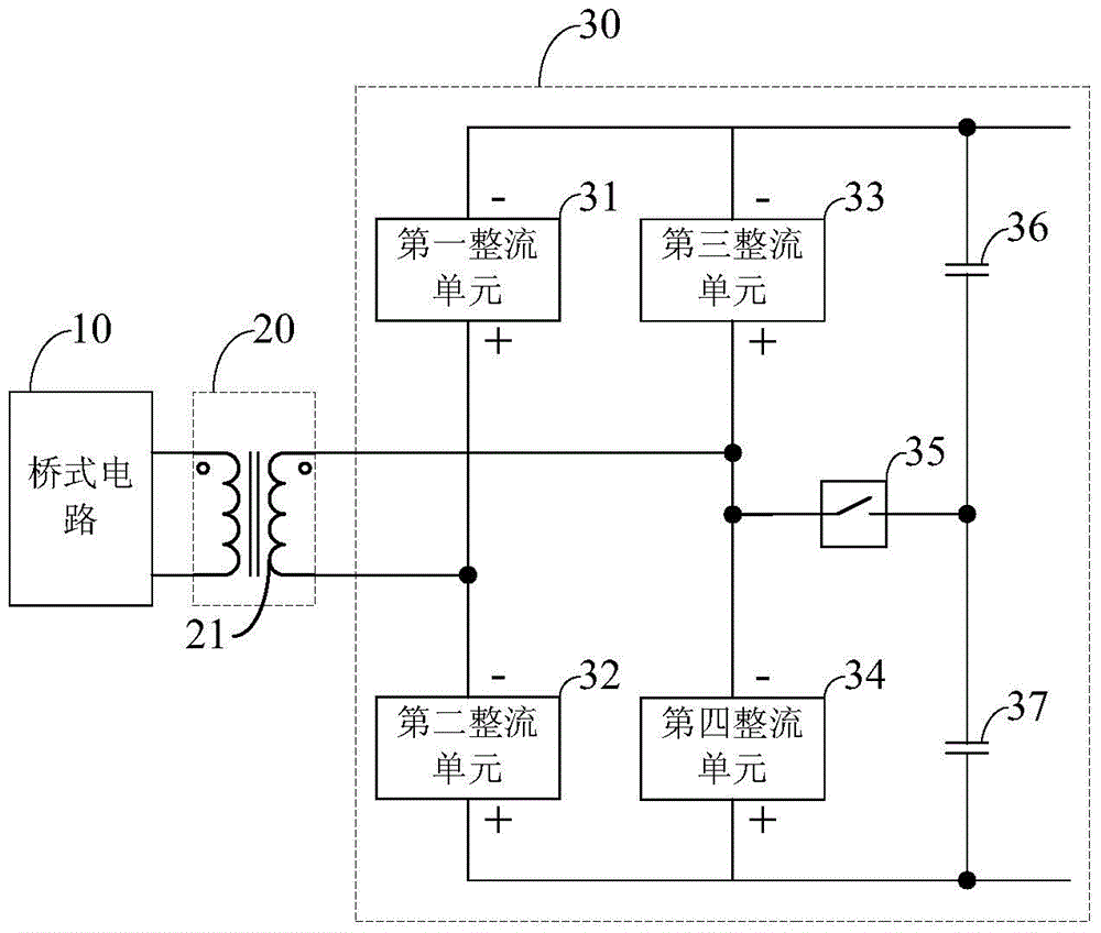
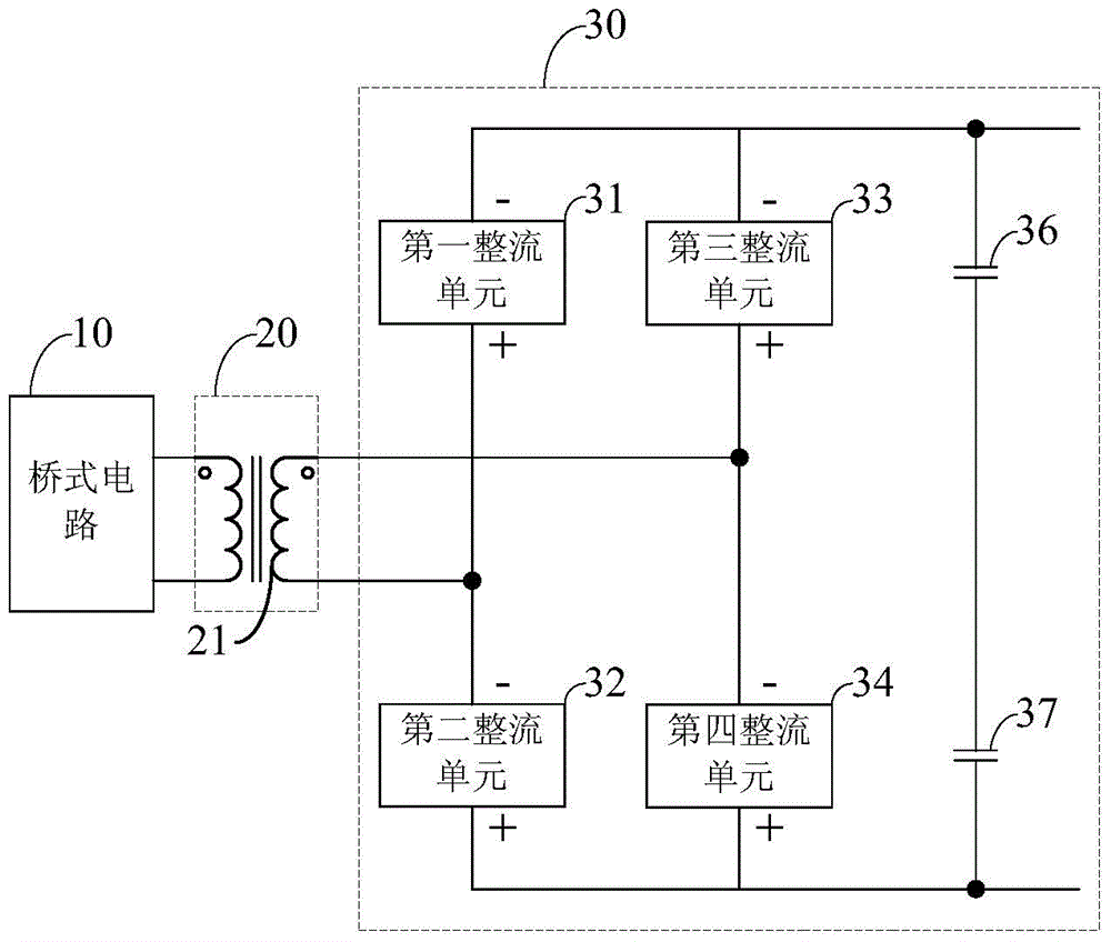
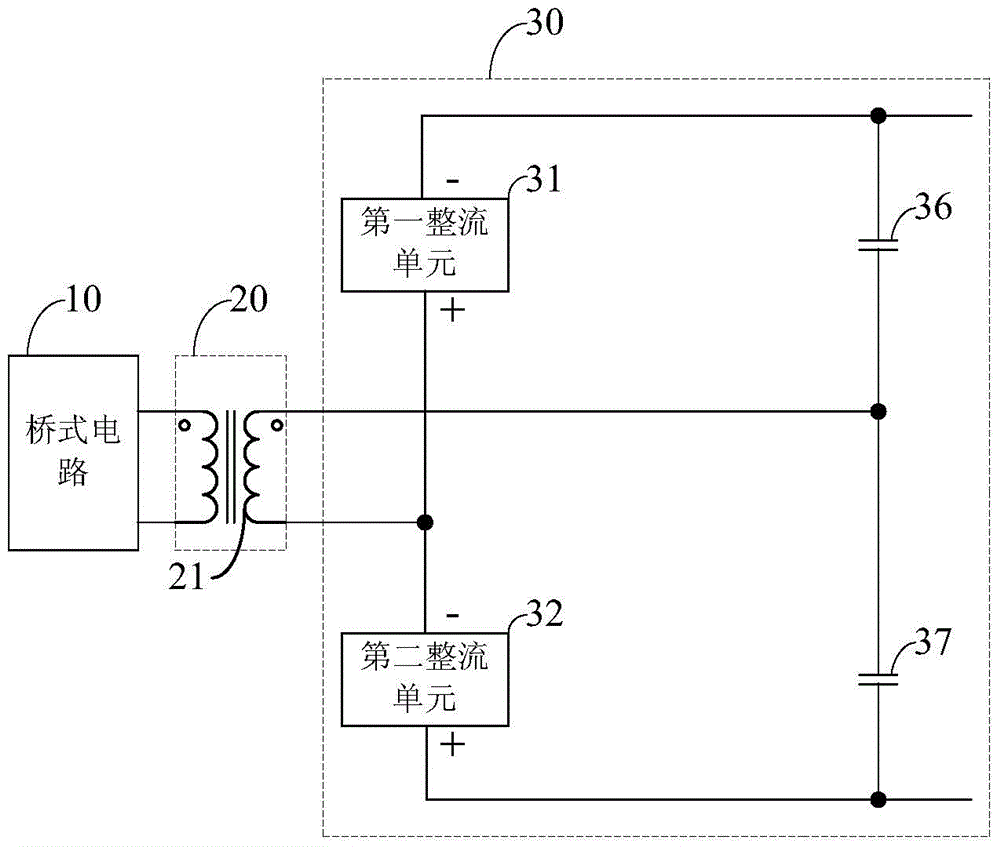
[0024] figure 1 It is a schematic diagram of the structure of the DC-DC conversion circuit provided in the first embodiment of the present invention, such as figure 1 As shown, the circuit includes: a bridge circuit 10, a transformer circuit 20, and a secondary rectifier circuit 30 connected in sequence; the secondary rectifier circuit...


PUM


Abstract

The invention provides a direct current to direct current conversion circuit comprising a bridge circuit, a variable voltage circuit and a secondary rectifying circuit which are sequentially connected. In the secondary rectifying circuit, a positive electrode of a first rectifying unit and a negative electrode of a second rectifying unit are connected with one end of a secondary winding of the variable voltage circuit, a positive electrode of a third rectifying unit, a negative electrode of a fourth rectifying unit and the other end of the secondary winding are connected with one end of a controllable switch, one end of a first capacitor and one end of a second capacitor are connected with the other end of the controllable switch, the other end of the first capacitor is connected with the negative electrodes of the first rectifying unit and the third rectifying unit, and the other end of the second capacitor is connected with the positive electrodes of the second rectifying unit and the fourth rectifying unit. By the aid of the scheme, based on different scenes, off and on of the controllable switch are controlled, secondary rectifying modes are switched, assistant adjustment of output voltage is realized, and conversion efficiency is ensured in the scene that input and output voltage is changed within a wide range.

Description

technical field [0001] The invention relates to the field of circuits, in particular to a DC-DC conversion circuit. Background technique [0002] A bridge topology is usually used in a switching power supply to perform direct current (DC for short)-direct current conversion. Specifically, the PWM bridge topology can adjust the DC gain of the topology by adjusting the duty cycle of the drive signal of the power switch, and the resonant bridge topology can adjust the DC gain of the topology by adjusting the frequency of the drive signal of the power switch, thereby realizing When different voltages are input, the output voltage is stabilized, or the output voltage can be adjusted within a certain range. It can be seen that in the current common switching power supply using bridge topology, the DC gain is adjusted by adjusting the driving signal of the power switch. [0003] However, based on the above-mentioned DC-DC conversion scheme, when the input voltage and / or the outpu...

Claims


Application Information

Patent Timeline
IPC IPC(8): H02M3/335
CPCH02M3/335H02M7/2176
Inventor 王再兴
Owner XIAN RUIXIN TECH CO LTD
Why Eureka
Try Eureka