Supercharge Your Innovation With Domain-Expert AI Agents!

Dose deformation error calculation method and system

A technology for transforming errors and doses, which can be used in calculations, radiation therapy, X-ray/γ-ray/particle radiation therapy, etc., and can solve problems such as increasing difficulty in transformation

Active Publication Date: 2018-03-30
KONINKLJIJKE PHILIPS NV
View PDF2 Cites 0 Cited by
  • Summary
  • Abstract
  • Description
  • Claims
  • Application Information

AI Technical Summary

Problems solved by technology

Difficulties with transitions due to movement or other deformation are multiplied when there is more than one preceding radiation delivery session, which must be combined in order to gain a complete understanding of the patient's radiation profile

Method used


Image

  • Dose deformation error calculation method and system
  • Dose deformation error calculation method and system
  • Dose deformation error calculation method and system

Examples


Embodiment Construction

[0018] The present disclosure describes methods and systems for planning radiation therapy treatments using a radiation therapy delivery system in conjunction with any one or more of various imaging system modalities. Such imaging system modalities include, for example, computed tomography (CT) imaging, cone beam CT, other x-ray based imaging, ultrasound imaging, magnetic resonance imaging (MRI), PET, and the like.

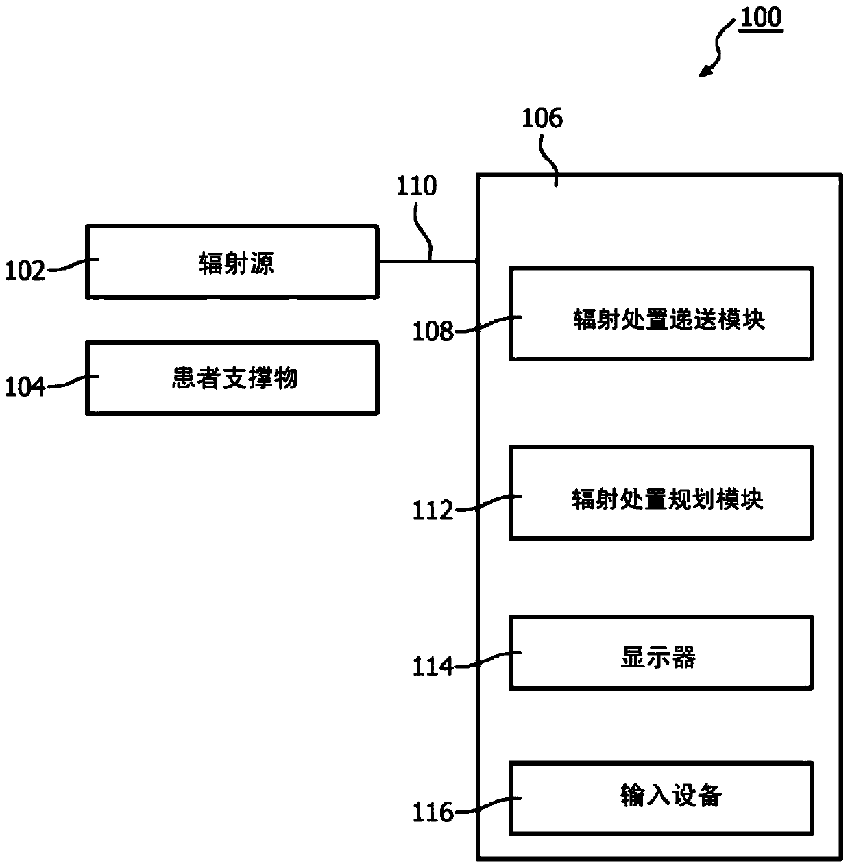
[0019] exist figure 1 A typical radiation therapy system 100 is schematically illustrated in . Accordingly, the system 100 includes a radiation source 102 for directing and delivering radiation to a designated target region(s) within a patient placed on a support 104 . For example, radiation source 102 may be an x-ray source or some other suitable source for providing radiation for radiation therapy. Radiation source 102 is mounted on a movable support structure (not shown) such that it can be maneuvered into various positions and orientations about the patient...


PUM


Abstract

A method and system are provided for determining radiation dose transformation errors in which there is deformation in one or more imaging structures recorded by at least one fixed image dataset and at least one moving image dataset. Corresponding landmark points in the fixed image and in the moving image are identified automatically or semi-automatically.

Description

technical field [0001] The present application generally relates to methods and systems for radiation therapy planning. Radiation therapy is the delivery of ionizing radiation to a patient, planned and performed by trained medical professionals. The purpose of radiation delivery can vary widely. Very commonly, the therapy is used to treat disease, eg, cancer, by ionizing the diseased tissue and thereby destroying it. A central goal of radiation therapy planning is to control radiation delivery to maximize radiation exposure to target regions within the patient's body (i.e., diseased tissue) while maximizing radiation exposure to non-target regions within the patient's body (i.e., healthy tissue) to minimize radiation exposure. Background technique [0002] As commonly practiced, radiation therapy begins with a detailed three-dimensional imaging scan (eg, a computed tomography (CT) scan) of the patient's body. Trained medical professionals often prescribe several characte...

Claims


Application Information

Patent Timeline
Patent Type & Authority Patents(China)
IPC IPC(8): G06T7/33A61N5/10A61B6/03
CPCG06T7/337G06T7/248A61N5/1031G06T2207/10081A61B6/035A61B6/469A61N5/1037A61N5/1071A61N2005/1072
Inventor K·A·布兹杜泽克M·D·维斯迈尔
Owner KONINKLJIJKE PHILIPS NV
Features
  • R&D
  • Intellectual Property
  • Life Sciences
  • Materials
  • Tech Scout
  • Unparalleled Data Quality
  • Higher Quality Content
  • 60% Fewer Hallucinations
Learn More