A cranial laser locator

A locator and laser technology, which is applied in stereotaxic surgical instruments, computerized tomography scanners, radiation beam guiding devices, etc., can solve the problems of prolonging the examination time of patients, heavy equipment, and poor fixation, so as to avoid repetitive scanning, The effect of shortening the inspection time and prolonging the service life

Active Publication Date: 2017-03-08
陕西汉德康医疗科技有限公司
View PDF9 Cites 0 Cited by
  • Summary
  • Abstract
  • Description
  • Claims
  • Application Information

AI Technical Summary

Problems solved by technology

[0002] At present, patients with cerebral hemorrhage need to undergo CT examination before minimally invasive hematoma evacuation. During CT examination, the patient's head needs to be placed on a headrest with arc-shaped grooves for CT examination, which is not easy to place in actual work. and fix the subject's head, resulting in a decline in the image quality of the CT head examination, and even the obtained image cannot help determine the position, and can only be scanned repeatedly, thereby prolonging the patient's examination time and increasing the patient's radiation dose. It also caused too much load to the CT machine, which affected the service life of the machine
In clinical work, due to the inconsistency of the scanning position, positioning through CT reading results in inaccurate positioning
Some are positioned by vernier calipers, because poor development of the scalp on CT also causes positioning errors
Some devices are bulky, hard to fix and require multiple scans

Method used


Image

  • A cranial laser locator
  • A cranial laser locator
  • A cranial laser locator

Examples


Embodiment 1

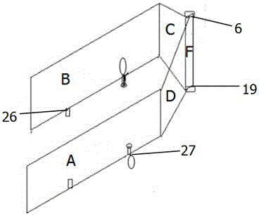
[0019] see figure 1 , the three-dimensional structure description of the head locator:

[0020] It is composed of rectangular frame A and rectangular frame B symmetrical on both sides, and rectangular frame C and rectangular frame D symmetrical on the front side. The plane formed by rectangular frame A, rectangular frame B, rectangular frame C and rectangular frame D is perpendicular to the base Plane, the base plane is composed of the lower edges of four rectangular frames, and the plane intersection line F of the rectangle frame C and the rectangle frame D is also perpendicular to the base plane, and the front line 9 of the intersection line is parallel to the plane intersection line F, and is connected with the coronal scaler Parallel and on the same plane, as a three-dimensional positioning marking line, the lower edges of the rectangular frame A and the rectangular frame B on both sides are symmetrical external ear hole fixers 26 and orbital rim fixers 27, thus forming a ...


PUM


Abstract

The invention discloses a head laser position finder which comprises a head position finder and laser frames. The head position finder comprises a rectangular frame A, a rectangular frame B, a rectangular frame C, a rectangular frame D, a front intersection line, fixators, an amplifier A, an amplifier B, a gear B, a fine adjustment screw knob A, a fine adjustment screw knob B, a gear A and a limiting tube. The rectangular frame A and the rectangular frame B are symmetrically arranged on two sides of the head laser position finder, the rectangular frame C and the rectangular framed D are symmetrically arranged on the front side of the head laser position finder, the corresponding fixators, the amplifier A, the amplifier B, the fine adjustment screw knob A, the gear A and the limiting tube are arranged on a coronal view calibrator at the rears of the rectangular frame C and the rectangular frame D, the corresponding fixator, the gear B and the fine adjustment screw knob B are arranged on a sagittal view calibrator, the laser frames include a laser frame A and a laser frame B, laser emitting pens A are arranged on the laser frame A, and laser emitting pens B are arranged on the laser frame B. The head laser position finder has the advantages that the heads of patients can be stably fixed by the aid of the head laser position finder with the structure, accordingly, the clearness of images can be guaranteed during scanning, repeated scanning can be prevented, the patient examination time can be shortened, radiation can be reduced, and the service life of the head laser position finder can be prolonged.

Description

technical field [0001] The invention relates to medical auxiliary equipment, in particular to a cranial laser locator. Background technique [0002] At present, patients with cerebral hemorrhage need to undergo CT examination before minimally invasive hematoma evacuation. During CT examination, the patient's head needs to be placed on a headrest with arc-shaped grooves for CT examination, which is not easy to place in actual work. and fix the subject's head, resulting in a decline in the image quality of the CT head examination, and even the obtained image cannot help determine the position, and can only be scanned repeatedly, thereby prolonging the patient's examination time and increasing the patient's radiation dose. Caused too much load to CT machine again, had influenced the service life of machine. In clinical work, due to the inconsistency of the scanning position, positioning through CT reading results in inaccurate positioning. Some use vernier calipers for positi...

Claims


Application Information

Patent Timeline
Patent Type & Authority Patents(China)
IPC IPC(8): A61B6/08A61B6/03A61B90/14
Inventor 周军
Owner 陕西汉德康医疗科技有限公司
Why Eureka
Try Eureka