Continuous cast extrusion molding device

A forming device and casting extrusion technology, which is applied in the field of metal material processing, can solve problems such as insufficient friction and affecting the quality of bars, and achieve the effects of smooth heating, improved ductility, and improved fineness

Active Publication Date: 2015-05-13
ZHANGJIAGANG CITY GUANGCHUAN ELECTRONICS
View PDF9 Cites 4 Cited by
  • Summary
  • Abstract
  • Description
  • Claims
  • Application Information

AI Technical Summary

Problems solved by technology

[0002] At present, the traditional continuous casting extrusion molding device only has casting extrusion grooves on the casting extrusion wheel, and there is no casting extrusion groove on the casting extrusion shoe. Since the casting extrusion wheel is rotating, it determines the various casting extrusion grooves on the casting extrusion wheel. The depth of the spot is consistent, which determines that the flow channel between the casting wheel and the casting shoe does not change, so that the friction between the grains of the metal in the hot melt state is not sufficient in the flow channel, thus affecting the bar. quality
In addition, since the hot gas formed during the cooling process of the metal in the hot melt state cannot be dissipated quickly at the opening of the runner, a small amount of air bubbles remain in the formed rod, which affects the quality of the rod

Method used


Image

  • Continuous cast extrusion molding device
  • Continuous cast extrusion molding device
  • Continuous cast extrusion molding device

Examples


Embodiment approach

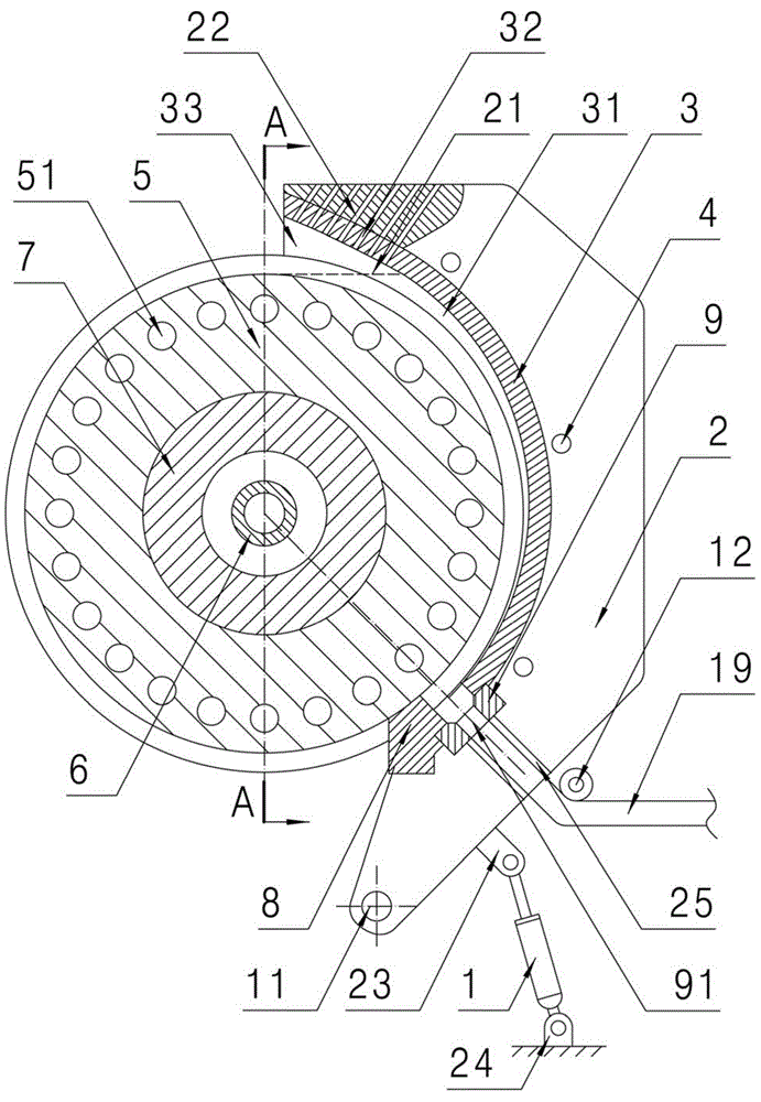
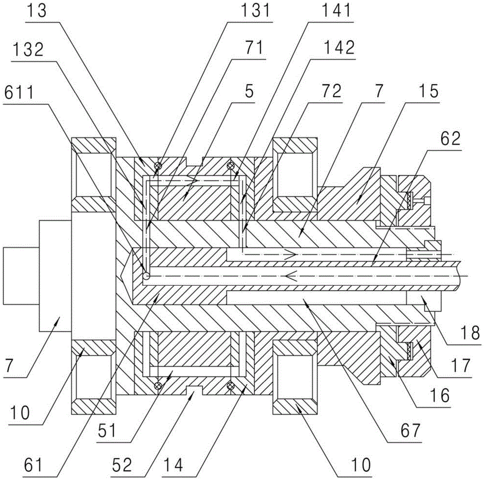
[0021] Such as figure 1 with figure 2 As shown, the continuous casting extrusion molding device of the present invention includes: a frame (which belongs to the conventional technology in the art, not shown in the figure), a rotating shaft 7 which is movably arranged on the frame by a pair of bearings 10, through The hinged shaft 11 is movably hinged to the cast extrusion shoe seat 2 on the frame, the axis line of the hinged shaft 11 is parallel to the axis line of the cast extrusion wheel 5, and the cast extrusion wheel 5 and the cast extrusion wheel 5 are arranged on the rotating shaft 7. The left side roller 13 (away from the water inlet side) and the right side roller 14 (closer to the water inlet side) on both sides, also on the right side of the right side bearing 10 on the rotating shaft 7, are successively provided with a pusher 15, an annular plunger 16 and An annular cylinder liner 17, an annular casting groove 52 is provided on the casting wheel 5, and a casting s...


PUM


Abstract

The invention discloses a continuous cast extrusion molding device. The continuous cast extrusion molding device is capable of dissipating heat sufficiently and enables metal grains to rub sufficiently. The continuous cast extrusion molding device comprises a rack, cast extrusion wheels and a cast extrusion boot base are movably arranged on the rack, annular cast extrusion grooves are formed in the cast extrusion wheels, and arc cast extrusion grooves matched with the annular cast extrusion grooves are arranged on the cast extrusion boot, a stopping block and a discharging mold which are matched with the annular cast extrusion grooves are arranged on the cast extrusion shoe plate, and the center of the section, corresponding to the center lines of a discharging mode hole and the annular cast extrusion grooves and the center of the section, corresponding to the center lines of the discharging mode hole and the arc cast extrusion grooves are located at the center line of the discharging mode hole. A diversion groove communicated with the arc cast extrusion groove is formed in the upper end of the arc cast extrusion groove, heat conduction holes communicated with the diversion groove are formed in the cast extrusion boot, and heat emission hole corresponding to the heat conduction holes one by one is formed in the cast extrusion boot base. The continuous cast extrusion molding device is used for manufacturing aluminium rods with high quality.

Description

technical field [0001] The invention relates to the field of metal material processing, in particular to a device for continuously casting and extruding metal in a hot melt state to finally form a rod. Background technique [0002] At present, the traditional continuous casting extrusion molding device only has casting extrusion grooves on the casting extrusion wheel, and there is no casting extrusion groove on the casting extrusion shoe. Since the casting extrusion wheel is rotating, the various casting extrusion grooves on the casting extrusion wheel are determined. The depth of the place is consistent, which determines that the flow channel between the casting wheel and the casting shoe does not change, so that the friction between the grains of the metal in the hot melt state is not sufficient in the flow channel, thus affecting the bar. quality. In addition, since the hot gas formed during the cooling process of the metal in the hot melt state cannot be dissipated quic...

Claims


Application Information

Patent Timeline
Patent Type & Authority Applications(China)
IPC IPC(8): B22D11/06
CPCB22D11/0611
Inventor 谢国锋谢晓雯
Owner ZHANGJIAGANG CITY GUANGCHUAN ELECTRONICS
Why Eureka
Try Eureka