
Yarn pressing device for plastic cylinder knitter shuttle

A technology of knitting machines and circular looms, applied in circular looms, looms, textiles, etc., can solve the problems of weft yarn scalding, weft yarn throwing, warp yarn being broken by weft ribbon, etc., to achieve stable resistance, reduce The effect of small friction and small contact surface

Inactive Publication Date: 2015-05-13
常州市永明机械制造有限公司
View PDF7 Cites 3 Cited by
  • Summary
  • Abstract
  • Description
  • Claims
  • Application Information

AI Technical Summary

Problems solved by technology

[0003] The original structure of the yarn pressing board for the shuttle of the circular loom is a structure where a piece of skin is pasted on the place where the yarn pressing board and the weft bobbin are in contact. If the surface is too large, it is easy to heat up and burn the weft yarn, causing the weft yarn to be thrown out, causing the warp yarn to be broken by the weft ribbon, and sometimes the situation is very serious

Method used


Image

  • Yarn pressing device for plastic cylinder knitter shuttle
  • Yarn pressing device for plastic cylinder knitter shuttle

Examples


Embodiment Construction

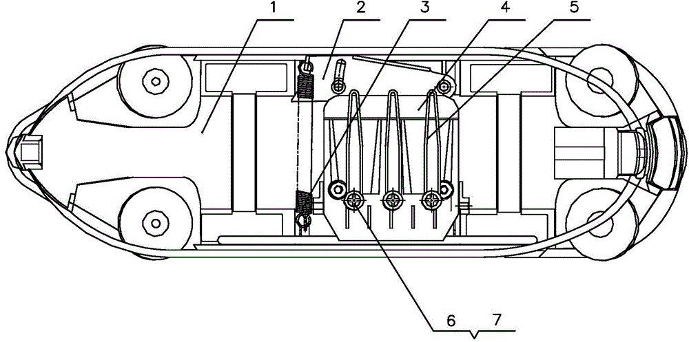
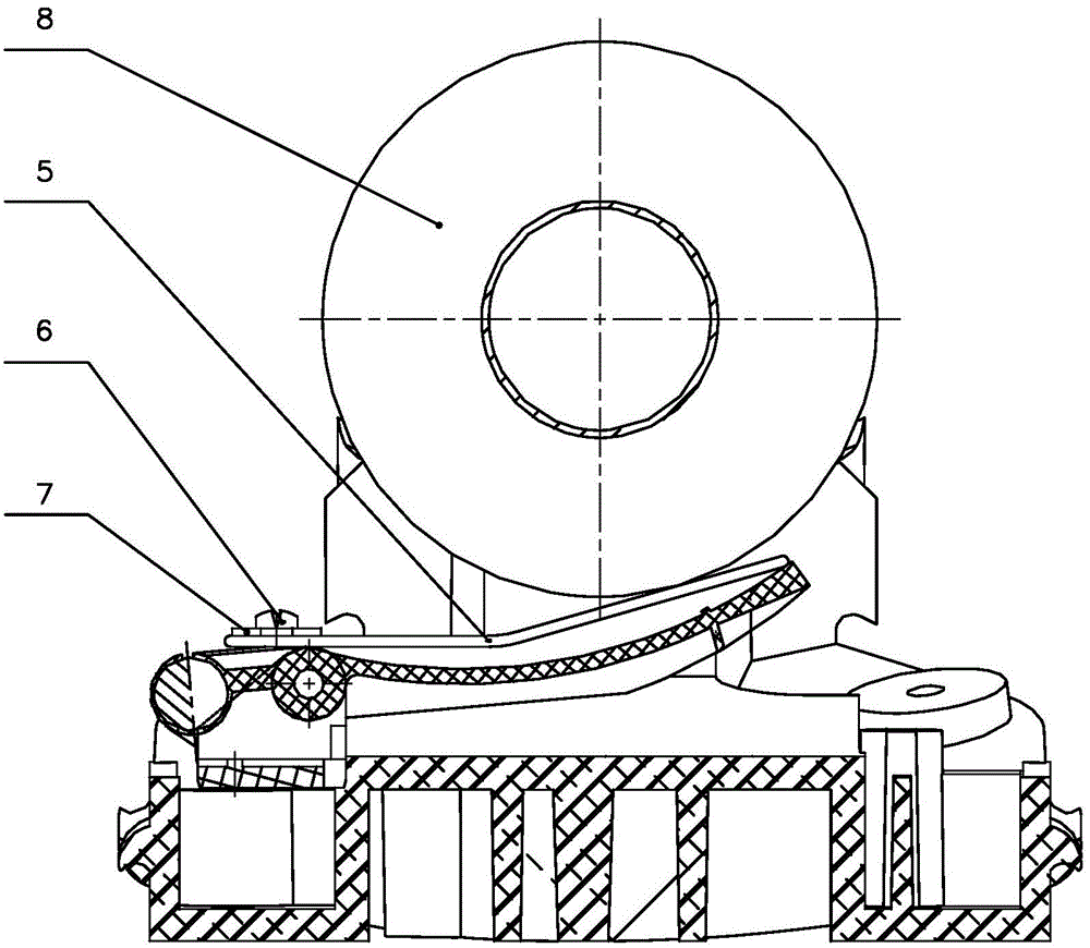
[0014] The present invention is described in further detail now in conjunction with accompanying drawing. These drawings are all simplified schematic diagrams, which only illustrate the basic structure of the present invention in a schematic manner, so they only show the configurations related to the present invention.

[0015] Such as figure 1 and 2 As shown, a yarn pressing device for the shuttle of a plastic circular loom is installed in the middle of the shuttle body 1 of the circular loom, and includes a yarn pressing plate 4, an extension spring seat 2 and an extension spring 3, and the extension spring seat 2 is installed on the In the shuttle body 1, one end of the extension spring 3 is hung on the extension spring seat 2, and the other end tightens the yarn pressing plate 4. The yarn pressing plate 4 is installed in the shuttle body 1, and a wire brush 5 is installed on the upper surface of the yarn pressing plate 4. The wire brush 5 is wound into a closed structure...


PUM


Abstract

The invention relates to a yarn pressing device for a plastic cylinder knitter shuttle. The yarn pressing device is installed in the middle in a cylinder knitter shuttle body. The yarn pressing device comprises a yarn pressing plate, a tension spring base and a tension spring. The tension spring base is installed in the shuttle body, one end of the tension spring is hung on the tension spring base, and the other end of the tension spring tensions the yarn pressing plate. The yarn pressing plate is installed in the shuttle body, and wire brushes are installed on the upper surface of the yarn pressing plate and are each of a flat enclosed structure formed by winding steel wires. Compared with an original yarn pressing plate structure, surface contact or line contact between a weft bobbin and a yarn pressing plate is changed into line contact or point contact between a weft bobbin and the steel brushes, abrasion to yarn is weakened, the situation that the yarn is burned and broken due to large-area friction heating is avoided, the resistance applied by the yarn pressing late to the weft bobbin through the steel brushes can be stable, and the tension produced by weft in the process of knitting can be constant.

Description

technical field [0001] The invention relates to the technical field of plastic cylinder knitting machines, in particular to a yarn pressing device for a plastic cylinder knitting machine shuttle. Background technique [0002] The yarn pressing device for the shuttle of the plastic circular loom is specifically a yarn pressing plate structure installed in the shuttle of the circular loom. The tension of the weft yarn can stop the rotation of the weft yarn bobbin quickly after the weft yarn breaks. [0003] The original structure of the yarn pressing board for the shuttle of the circular loom is a structure where a piece of skin is pasted on the place where the yarn pressing board and the weft bobbin are in contact. If the surface is too large, it is easy to heat up and burn the weft yarn, causing the weft yarn to be thrown out and causing the warp yarn to be broken by the weft ribbon. Sometimes the situation is very serious. In order to prevent the weft yarn from being scal...

Claims


Application Information

Patent Timeline
IPC IPC(8): D03D37/00
CPCD03D37/00
Inventor 何敏
Owner 常州市永明机械制造有限公司
Learn More