towel dyeing machine

A technology for dyeing machines and towels, which is applied in the field of towel dyeing machines. It can solve the problems of low liquor ratio and dyeing efficiency, dyeing solution blowing over, and more costs, etc., and achieves convenient replacement, daily maintenance, and cyclic operation. Smooth, reduce the effect of skid chance

Active Publication Date: 2016-10-12
FONGS NAT ENG (SHENZHEN) CO LTD
View PDF5 Cites 0 Cited by
  • Summary
  • Abstract
  • Description
  • Claims
  • Application Information

AI Technical Summary

Problems solved by technology

Although this design reduces the amount of dyeing solution, the coloring efficiency is still significantly different from the traditional bath dyeing, and the two important elements of low bath ratio and coloring efficiency cannot be taken into account at the same time.
[0003] In addition, the fabric dyeing machines developed in the prior art generally focus on finishing lightweight materials and materials sensitive to wrinkles, and reduce the number of dyeing and finishing devices for heavy fabrics such as terry cloth.
The existing dyeing and finishing machine technology generally lifts the fabric to the nozzle throat on the top of the main cylinder, and the dye solution is directly sprayed onto the surface of the fabric to spread. So that the fabric cannot be blown over by the dye liquor like light fabrics, and the uniformity of dye liquor absorption by light fabrics cannot be achieved. increased water consumption

Method used


Image

  • towel dyeing machine
  • towel dyeing machine
  • towel dyeing machine

Examples


Embodiment Construction

[0051] The present invention will be further elaborated below through the accompanying drawings and the embodiments of the present invention.

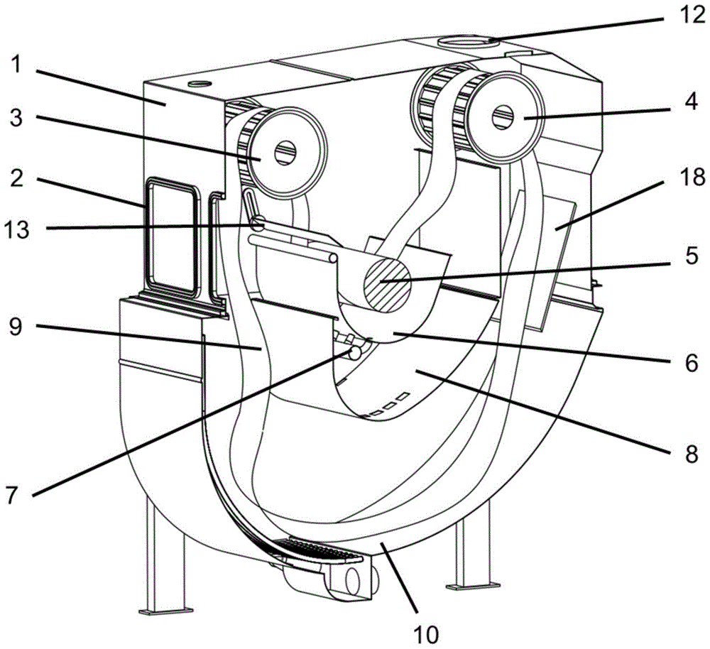
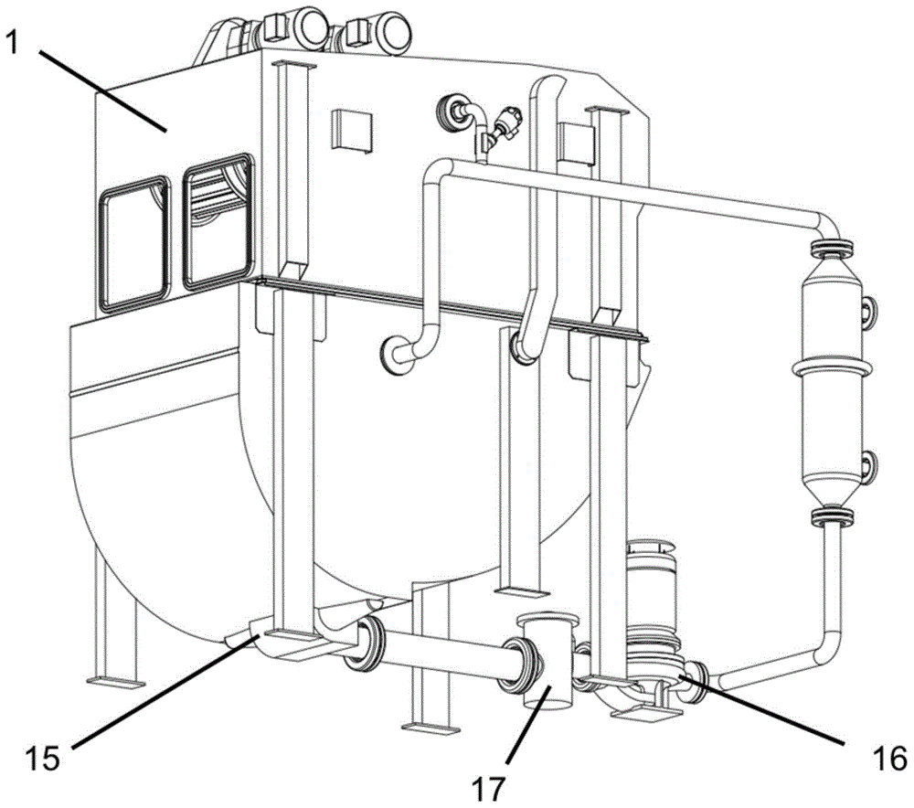
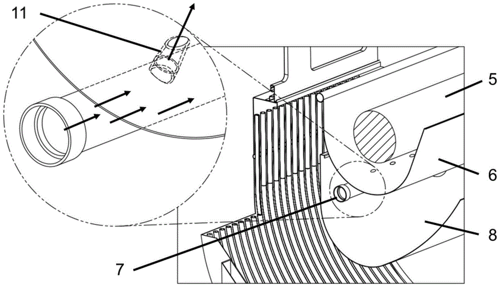
[0052] The structure of the present embodiment towel dyeing machine is as figure 1 is shown in the partial cross-sectional view. This embodiment comprises a main housing 1 of a dyeing machine. There is a working door 2 on the front side of the dyeing machine. There are a lifting drum 3 and an auxiliary lifting drum 4 inside the dyeing machine. There is a dyeing auxiliary tank 6 between the two drums. There is a passive roller 5 inside, and the fabric entering the secondary groove passes through the bottom of the passive roller. A row of nozzle throats 7 is connected to the bottom of the auxiliary tank, and the dye liquor in the dyeing machine is sprayed onto the fabric by spraying. There is also a dividing plate 8 in the dyeing machine to separate the dyeing sub-trough and the dyeing bottom tank 10 at the bottom, so as to prevent clo...


PUM


Abstract

The invention discloses a towel dyeing machine. The towel dyeing machine comprises a main shell body (1), a dyeing bottom slot (10), a dyeing sub slot (6), a hoisting drum (3), a sub hoisting drum (4) and a cloth placing device. The dyeing sub slot (6) is installed above the dyeing bottom slot (10). A row of nozzles is transversely arranged on the inner wall of the bottom of the dyeing sub slot (6). The volume of the dyeing sub slot (6) is smaller than the volume of the bottom slot, and the dyeing sub slot (6) is provided with a driven drum (5). The inlet of the towel dyeing machine is provided with a sensor (13) and the cloth placing device. The surfaces of the hoisting drum (3) and the sub hoisting drum (4) are non-smooth ripple-shaped. The main shell body (1) of the dyeing machine is provided with an operating door (2) and a maintenance door (12), so that the dyeing machine is convenient to operate and repair. According to the towel dyeing machine, the uniformity of dyeing liquor adsorption of towel-like textiles is improved, the usage amount of dyeing liquor, water and electricity is reduced, the volume of the dyeing machine is small, the expenditure and emission reduction is achieved, and the dyeing machine is widely applicable to the dyeing technology of heavy textiles.

Description

technical field [0001] The invention relates to a dyeing and finishing device, in particular to a towel dyeing machine. Background technique [0002] In the field of dyeing and finishing technology, increasing the contact time of fabrics with dyeing liquor is a necessary condition to ensure coloring. However, under the current standards of environmental protection and emission reduction, new dyeing machines use nozzles to concentrate the dye solution on the circulating fabric. The fabric usually circulates in the dyeing machine in the shape of a cloth rope and is scattered in the dyeing bottom tank. The cloth rope is pulled up by the lifting drum and guided to the nozzle throat. After being sprayed by the dye liquor, it falls back to the dyeing bottom trough. This is a continuous cycle, so that the entire piece of cloth connected head to tail is repeatedly contacted with the dye liquor to be colored. A kind of dyeing machine arrangement with double cylinder is disclosed as ...

Claims


Application Information

Patent Timeline
Patent Type & Authority Patents(China)
IPC IPC(8): D06B3/10D06B23/20D06B23/04
CPCD06B3/10D06B23/04D06B23/20
Inventor 徐达明
Owner FONGS NAT ENG (SHENZHEN) CO LTD
Why Eureka
Try Eureka