
Novel steam atomization device

An atomizing device and steam technology, which are applied in washing devices, steam generation, steam generation methods, etc., can solve the problems of difficult processing, inconvenient processing, and cumbersome use of irons, and achieve good atomization effect, low cost, and ease of use. processing effect

Inactive Publication Date: 2015-05-13
深圳市好运达电器有限公司
View PDF6 Cites 0 Cited by
  • Summary
  • Abstract
  • Description
  • Claims
  • Application Information

AI Technical Summary

Problems solved by technology

[0002] At present, the pressure steam irons used in the market, whether they are hanging irons or flat irons, because the traditional heating body is made of aluminum material, the aluminum material at high temperature is easily oxidized when water or steam passes through, and scale will be generated after oxidation. Scale covers the surface of the aluminum heating body, so that the heat inside the heating body cannot be transmitted, and the heat utilization rate of the heating body is reduced.
For this reason, stainless steel heating elements, copper heating elements and the like developed on this basis are not easy to oxidize or produce scale heating elements, but the weight of copper or stainless steel is much larger than aluminum, and the iron is heavy and heavy to use in the hand. Inconvenient to process, difficult to process, and high material cost

Method used


Image

  • Novel steam atomization device
  • Novel steam atomization device

Examples


Embodiment Construction

[0011] The present invention will be described in further detail below in conjunction with the accompanying drawings.

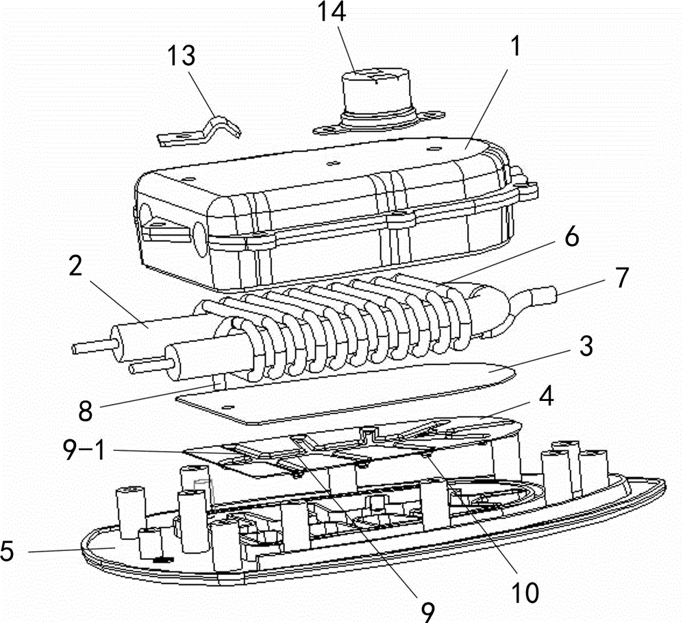
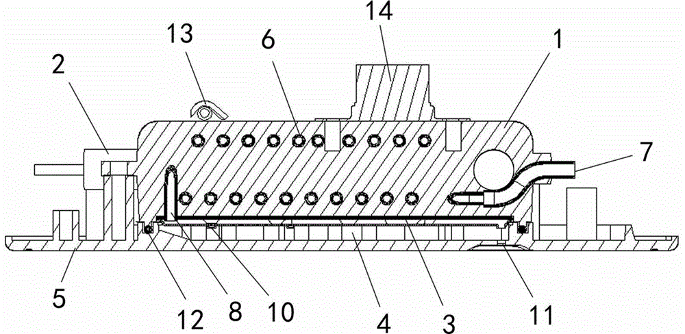
[0012] Such as figure 1 , figure 2 As shown, a new steam atomization device is characterized in that it includes an aluminum heating body 1, a heating pipe 2, a heat conducting plate 3, a steam circulation plate 4 and an iron soleplate 5, and the heating pipe 2 is built in the aluminum heating body 1, The heat pipe 2 is wound with a steam channel 6, one end of the steam channel 6 is a water inlet 7, and the other end is a steam outlet 8; the bottom of the aluminum heating body 1 is die-cast with a heat conduction plate 3, and the bottom surface of the heat conduction plate 3 is provided with a steam circulation plate 4. The steam circulation plate 4 is provided with a steam flow groove 9, and the steam flow groove 9 is provided with several branch grooves 9-1, and the end of the branch groove 9-1 is provided with a steam outlet 2 10, and the heat conduction...


PUM


Abstract

The invention discloses a novel steam atomization device which comprises an aluminum heating body, a heating pipe, a heat conducting plate, a steam circulating plate and an iron bottom plate. The heating pipe is placed in the aluminum heating body. A steam channel is arranged on the heating pipe in a winding mode. One end of the steam channel is a water inlet. The other end of the steam channel is a first steam outlet. The heat conducting plate is arranged at the bottom of the aluminum heating body in a pressure-casting mode. The steam circulating plate is arranged at the bottom face of the heat conducting plate. A steam circulating groove is formed in the steam circulating plate and is provided with a plurality of branch grooves. Second steam outlets are formed in the tail ends of the branch grooves. The heat conducting plate and the steam circulating plate form a sealed steam flowing groove. The first steam outlet is communicated with the steam flowing groove through the heat conducting plate. Third steam outlets corresponding to the second steam outlets in position are formed in the iron bottom plate. Sealing silica gel is arranged at the connection portion of the aluminum heating body and the iron bottom plate. Compared with the prior art, the novel steam atomization device has the advantages that during using, incrustation cannot be generated easily in the whole steam generating device, so that the heat using rate is not affected, weight is low, machining is easy, cost is low, and atomization effect is good.

Description

technical field [0001] The invention relates to a steam generating device, in particular to a steam atomizing device, which belongs to accessories on steam irons, garment irons, portable garment irons and steam cleaners. Background technique [0002] At present, the pressure steam irons used in the market, whether they are hanging irons or flat irons, because the traditional heating body is made of aluminum material, the aluminum material at high temperature is easily oxidized when water or steam passes through, and scale will be generated after oxidation. Scale covers the surface of the aluminum heating body, so that the heat inside the heating body cannot be transmitted, and the heat utilization rate of the heating body is reduced. For this reason, stainless steel heating elements, copper heating elements and the like developed on this basis are not easy to oxidize or produce scale heating elements. It is inconvenient to process, the process is difficult, and the material...

Claims


Application Information

Patent Timeline
IPC IPC(8): F22B1/28D06F75/10
Inventor 张进功
Owner 深圳市好运达电器有限公司
Learn More