
Heat exchanger with thermal storage function

一种热交换器、热交换管的技术,应用在加热方式、蓄热设备、间接换热器等方向,达到防止蓄热材料泄漏的效果

Inactive Publication Date: 2015-05-13
KEIHIN THERMAL TECH CORP
View PDF9 Cites 4 Cited by
  • Summary
  • Abstract
  • Description
  • Claims
  • Application Information

AI Technical Summary

Problems solved by technology

[0008] Usually, the two metal plates constituting the above-mentioned cold storage material container can be manufactured by performing press work on the metal raw material plate using two metal molds having a shape corresponding to the final shape, but in this case, it is unavoidable that there is a gap between the two metal plates. There is a gap between the inner peripheral surface of the cylindrical hole formed by the semi-cylindrical part of the plate and the plug

Method used


Image

  • Heat exchanger with thermal storage function
  • Heat exchanger with thermal storage function
  • Heat exchanger with thermal storage function

Examples


Embodiment Construction

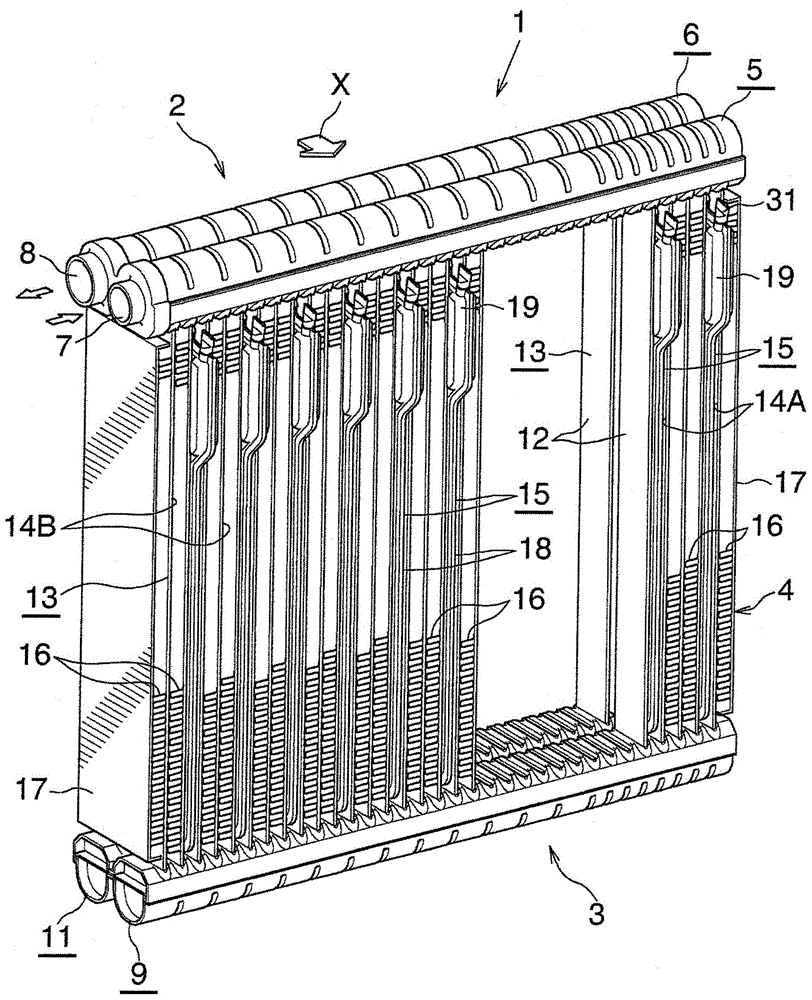
[0047] Hereinafter, embodiments of the present invention will be described with reference to the drawings. In this embodiment, the heat exchanger with a heat storage function of the present invention is applied to an evaporator with a cool storage function having a function of storing cold energy.

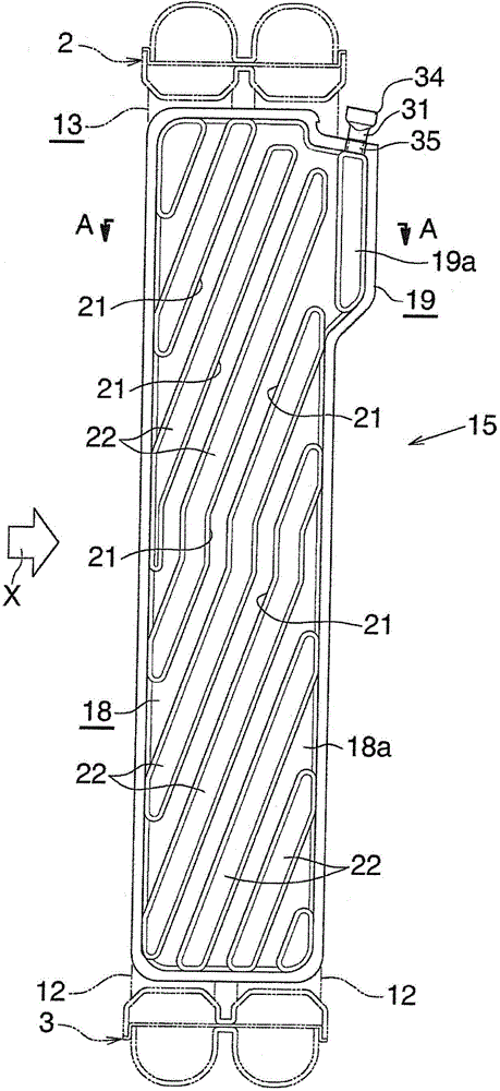
[0048] In the following description, the downstream side of the ventilation direction ( figure 1 and figure 2 The direction indicated by the arrow X) is the front, the opposite side is the rear, and the up and down, left and right, that is, when viewed from the front to the rear figure 1 Up and down, left and right are up and down, left and right.

[0049] Furthermore, in the following description, the term "aluminum" includes not only pure aluminum but also aluminum alloys.

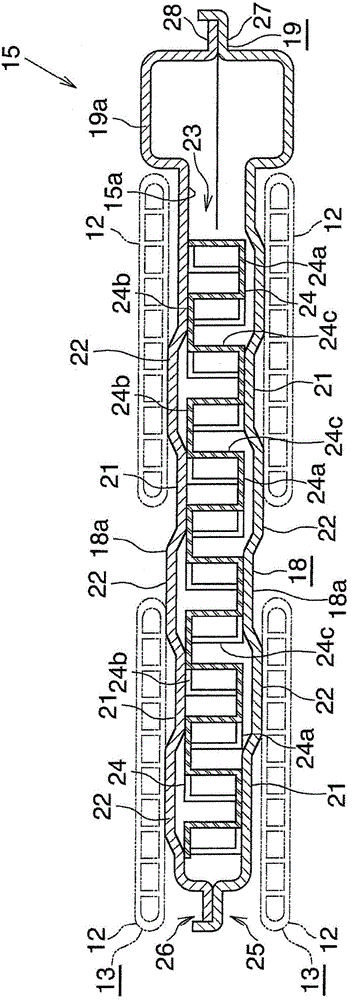
[0050] figure 1 Represent the overall structure of the evaporator with cold storage function of the present invention, Figure 2 to Figure 7 Indicates the structure of its main part. in addition, Fig...


PUM


Abstract

A cylindrical hole is formed between peripheral belt portions of two container constituent plates of a thermal storage material container of an evaporator with a cool storage function. A cylindrical portion of a thermal storage material charging member having a thermal storage material charging passage is disposed in the cylindrical hole and brazed to the two container constituent plates. That portion of the thermal storage material charging member which protrudes from the cylindrical hole includes a crushed portion and a cylindrical uncrushed portion. The crushed portion seals the thermal storage material passage. The cylindrical portion of the thermal storage material charging member is smaller in outside diameter than the uncrushed portion, and the cylindrical portion and the uncrushed portion have the same inside diameter. The cylindrical portion has an inward protrusion protruding into a thermal storage material containing space, and the inward protrusion has a radially expanding engagement portion.

Description

technical field [0001] The invention relates to a heat exchanger with heat storage function and a manufacturing method thereof. Background technique [0002] For example, for the purpose of environmental protection, improvement of fuel consumption of automobiles, etc., there have been proposed automobiles which automatically stop their engines when they are stopped at traffic lights or the like. [0003] However, in a normal car air conditioner, if the engine is stopped, the compressor driven by the engine will also be stopped, so there is a possibility that the refrigerant (the medium for transporting cooling energy) cannot be supplied to the evaporator, resulting in a sharp drop in cooling capacity. The problem. [0004] Then, in order to solve such a problem, it is conceivable to give the evaporator a cold storage function, and when the engine stops and the compressor stops, the cold energy stored in the evaporator is released to cool the vehicle interior. [0005] As s...

Claims


Application Information

Patent Timeline
Patent Type & Authority Applications(China)
IPC IPC(8): F25B39/02F28D20/00B23P15/26
CPCB23P15/26F25B39/02F25B2339/02F28D20/0034F24F5/0021F25B39/022F25B2400/24Y02E60/14Y10T29/49359
Inventor 鸭志田理信末满
Owner KEIHIN THERMAL TECH CORP
Learn More