Photographic fixing device and roller thereof

A technology of rollers and hollow tubes, applied in electrography, optics, instruments, etc., can solve problems such as low heat transfer efficiency, uneven temperature distribution on the surface of rollers, increased manufacturing costs and manufacturing difficulties, etc.

Active Publication Date: 2015-05-13
TECO IMAGE SYST
View PDF9 Cites 1 Cited by
  • Summary
  • Abstract
  • Description
  • Claims
  • Application Information

AI Technical Summary

Problems solved by technology

[0008] The main purpose of the present invention is to provide a fixing device and its rollers to solve the problem of low heat transfer efficiency and uneven temperature distribution on the surface of the rollers in t...

Method used


Image

  • Photographic fixing device and roller thereof
  • Photographic fixing device and roller thereof
  • Photographic fixing device and roller thereof

Examples


Embodiment Construction

[0041] Some typical embodiments embodying the features and advantages of the present invention will be described in detail in the description in the following paragraphs. It should be understood that the present invention can have various changes in different aspects, all of which do not depart from the scope of the present invention, and the description and drawings therein are used as illustrations in nature rather than limiting the present invention .

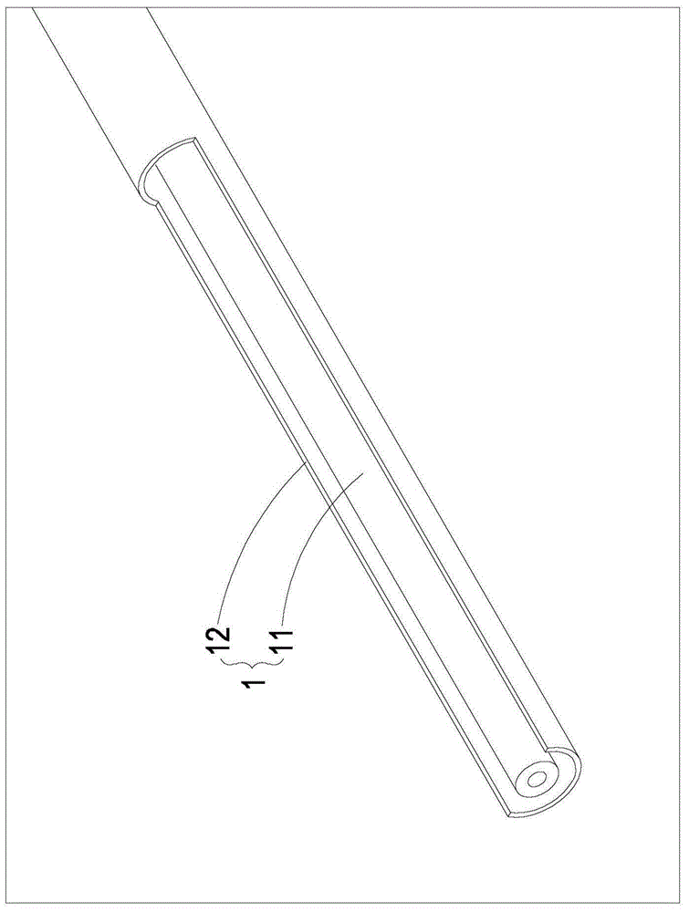
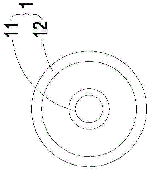
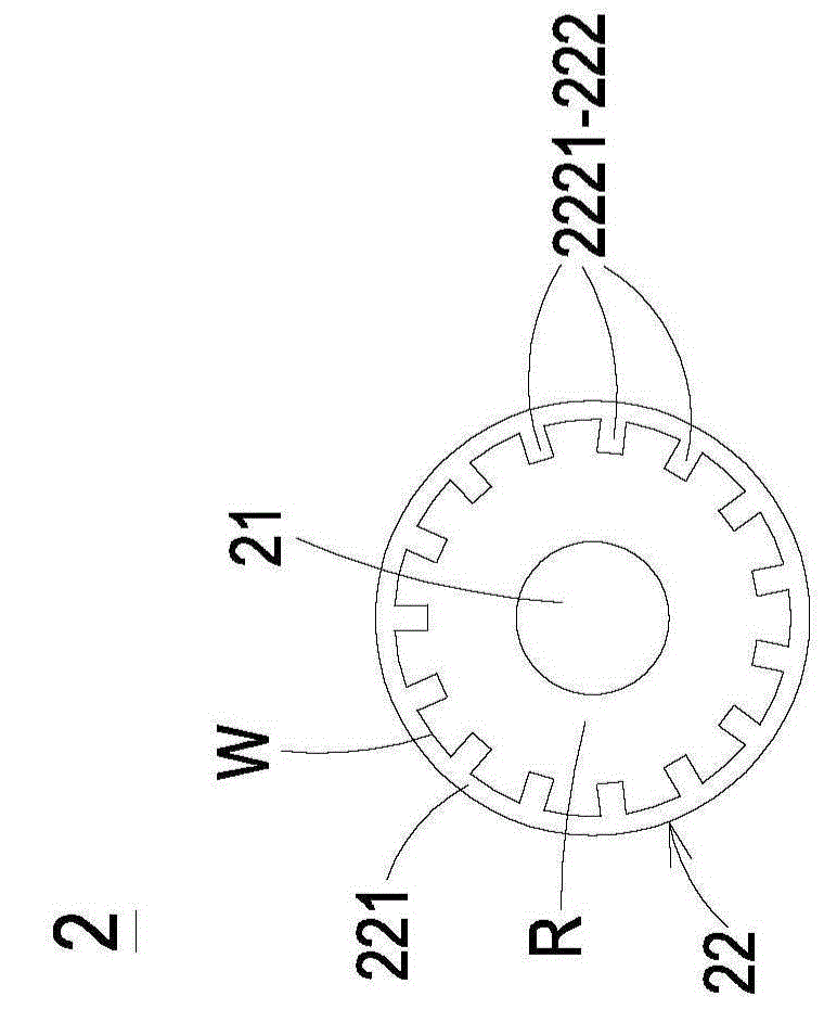
[0042] see Figure 2A , which is a front view of a fixing device according to a preferred embodiment of the present invention. Such as Figure 2A As shown, the fixing device 2 of the preferred embodiment of the present invention includes a heating element 21 and a roller 22 , the heating element 21 is configured to emit heat, and the roller 22 includes a hollow tube body 221 and an air disturbance structure 222 . Wherein, the hollow tube body 221 is disposed around the outer side of the heating element 21 and at least par...


PUM


Abstract

The invention provides a photographic fixing device which includes a heating element and a roller, the heating element is arranged for emitting heat energy, and the roller comprises a hollow tube body and an air turbulence structure. The hollow tube body is annularly arranged on the outer side of the heating element, and at least partially coats the heating element, an annular region is defined between the hollow tube body and the heating element, and the air turbulence structure is formed on the inner wall of the hollow tube body, and is arranged for disturbing air to convect in the annular region during rotation of the hollow tube body to promote heat transfer efficiency of heat transfer to the hollow tube body, so that the effects of improvement of the heat transfer efficiency and homogeneous temperature distribution of the roller surface can be achieved so as to effectively reduce the power wattage and energy consumption of the heating element.

Description

technical field [0001] The invention relates to a fixing device, in particular to a fixing device and rollers thereof. Background technique [0002] Laser printers are currently the most widely used printing equipment in enterprises and schools. The imaging generation principle is that after the paper is introduced, the laser diode unit will project the laser light containing the image data onto the photosensitive roller, and at the same time, the toner cartridge will be transferred to the photosensitive roller by the roller. The toner is attached to the imaging area of ​​the photosensitive roller, and the toner on the imaging area can be attached to the paper by rotating the photosensitive roller. Finally, the toner is fixed on the paper through the heating and pressure of the fixing device. [0003] In other words, the main imaging method of a laser printer is to use a fixing device to fix toner by means of heating and pressure. Among them, the heating method mostly uses...

Claims


Application Information

Patent Timeline
IPC IPC(8): G03G15/20
CPCG03G15/2042G03G15/2053
Inventor 陈加伟
Owner TECO IMAGE SYST
Why Eureka
Try Eureka