

Switch power supply and rectifying circuit
A technology of rectifier circuit and switching tube, which is applied to electrical components, AC power input to DC power output, output power conversion devices, etc., can solve the problems of low conversion efficiency and complicated control methods, and achieve the goal of reducing conversion efficiency The impact, the control method is simple, and the effect of preventing the bridge arm from passing through
- Summary
- Abstract
- Description
- Claims
- Application Information
AI Technical Summary
Problems solved by technology
Method used
Image

Examples
Embodiment Construction
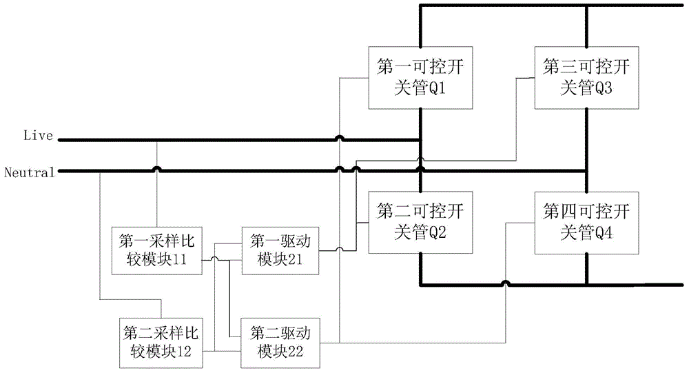
[0027] figure 2 It is a logic diagram of Embodiment 1 of the rectification circuit of the present invention. The rectification circuit includes: a first controllable switch tube Q1, a second controllable switch tube Q2, a third controllable switch tube Q3, a fourth controllable switch tube Q4, The first sampling comparison module 11 , the second sampling comparison module 12 , the first driving module 21 and the second driving module 22 . Wherein, the first controllable switch tube Q1, the second controllable switch tube Q2, the third controllable switch tube Q3, and the fourth controllable switch tube Q4 are all connected in antiparallel with diodes (not shown), or, the first controllable switch tube Q2 The switch tube Q1, the second controllable switch tube Q2, the third controllable switch tube Q3, and the fourth controllable switch tube Q4 all have equivalent diodes in the body, and the second end of the first controllable switch tube Q1 is connected to the second The fi...
PUM
 Abstract
Description
Claims
Application Information