Fluid container, in particular hydraulic reservoir for a motor-pump unit

A fluid container and pump unit technology, applied in the field of hydraulic tanks, can solve the problems of reduced working efficiency, mixing of air and hydraulic oil, etc., and achieve the effect of avoiding the formation of foam

Active Publication Date: 2015-05-13
TRW AUTOMOTIVE GMBH
View PDF10 Cites 3 Cited by
  • Summary
  • Abstract
  • Description
  • Claims
  • Application Information

AI Technical Summary

Problems solved by technology

This can in some cases lead to vigorous mixing of air and hydraulic oil, resulting in foam formation
The air bound in the foam is then sucked in by the pump of the motor-pump unit and the working efficiency of the system is significantly reduced

Method used


Image

  • Fluid container, in particular hydraulic reservoir for a motor-pump unit
  • Fluid container, in particular hydraulic reservoir for a motor-pump unit
  • Fluid container, in particular hydraulic reservoir for a motor-pump unit

Examples


Embodiment Construction

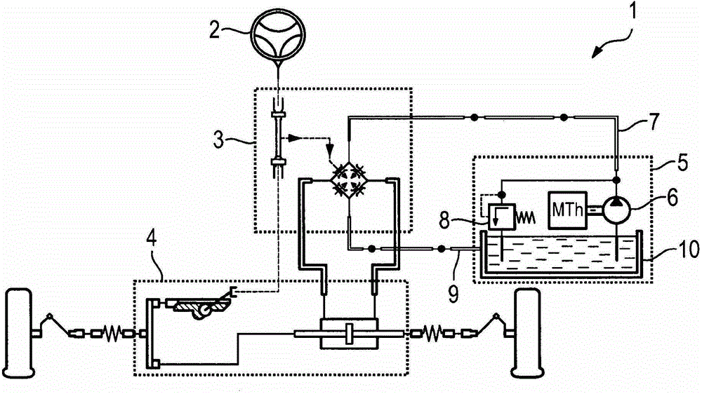
[0025] figure 1 A schematic diagram of an electrohydraulic vehicle steering system 1 is shown, comprising a steering wheel 2 , which is coupled in a known manner to a steering gear 4 via a servo valve 3 . Furthermore, a motor-pump unit 5 is provided which forms the interface between the electric and hydraulic parts of the electrohydraulic vehicle steering system 1 and which comprises a pump 6 which supplies the hydraulic circuit 7 with a supply from a hydraulic tank 10 in a known manner. Hydraulic oil in the form of a fluid container. The pump 6 has a pressure relief valve 8 , through which the fluid flow returns directly from the pressure side of the pump 6 into the hydraulic tank 10 . Furthermore, the hydraulic oil returned by the hydraulic circuit as a return flow 9 is fed to a hydraulic tank 10 .

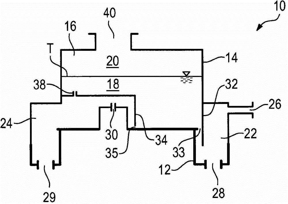
[0026] figure 2 , 4 , 5 and 6 show a first embodiment of a fluid container according to the invention in the form of a hydraulic tank 10 for a motor-pump unit 5 . The hydr...


PUM


Abstract

A fluid container, in particular a hydraulic reservoir (10) for a motor-pump unit, comprises a compensation chamber (16) that can contain a supply of fluid and air (20), and at least one return flow chamber into which a return flow of the fluid can flow, a flow connection being provided between the return flow chamber and the compensation chamber (16). The return flow chamber is provided with a suction port (28, 29) for a pump, in particlar of the motor-pump unit.

Description

technical field [0001] The invention relates to a fluid container, in particular a hydraulic tank for a motor-pump unit. Background technique [0002] In electrohydraulic vehicle steering systems a motor pump unit is used which supplies a hydraulic circuit with hydraulic oil from a hydraulic tank. Space constraints and cost-reduction measures make it necessary to dispense with the normally used additional, higher-arranged compensation tank for the hydraulic oil and to use a one-piece and at the same time smaller tank instead. The high power required in modern systems of the motor-pump unit results in an increased hydraulic oil volume flow, which flows at high speed into the tank, which also contains a compensating volume filled with air. This can in some cases lead to vigorous mixing of air and hydraulic oil, thereby leading to foam formation. The air bound in the foam is then sucked in by the pump of the motor-pump unit and the operating efficiency of the system is signif...

Claims


Application Information

Patent Timeline
Patent Type & Authority Applications(China)
IPC IPC(8): F15B1/26B62D5/06
CPCB62D5/062F15B1/26F15B21/047Y10T137/85978B62D5/064B62D5/07
Inventor M·默察拉G·黑斯默尔
Owner TRW AUTOMOTIVE GMBH
Why Eureka
Try Eureka