condenser

一种冷凝器、制冷剂的技术,应用在蒸发器/冷凝器、制冷机、制冷组件等方向,能够解决制造成本增大、阻碍应用、冷凝器、收集器和过冷器复杂等问题,达到避免重新加热、提高系统性能的效果

Active Publication Date: 2016-08-24
MAHLE INT GMBH
View PDF1 Cites 0 Cited by
  • Summary
  • Abstract
  • Description
  • Claims
  • Application Information

AI Technical Summary

Problems solved by technology

[0008] The disadvantage of the devices of the prior art is that the integration of the condenser, collector and subcooler in a stacked plate configuration has hitherto been realized in a very complicated manner
In addition to being complex in construction, prior art condensers are also characterized by increased manufacturing costs
Therefore more expense is incurred in case of application of condenser, which hinders its application

Method used


Image

  • condenser
  • condenser
  • condenser

Examples


Embodiment Construction

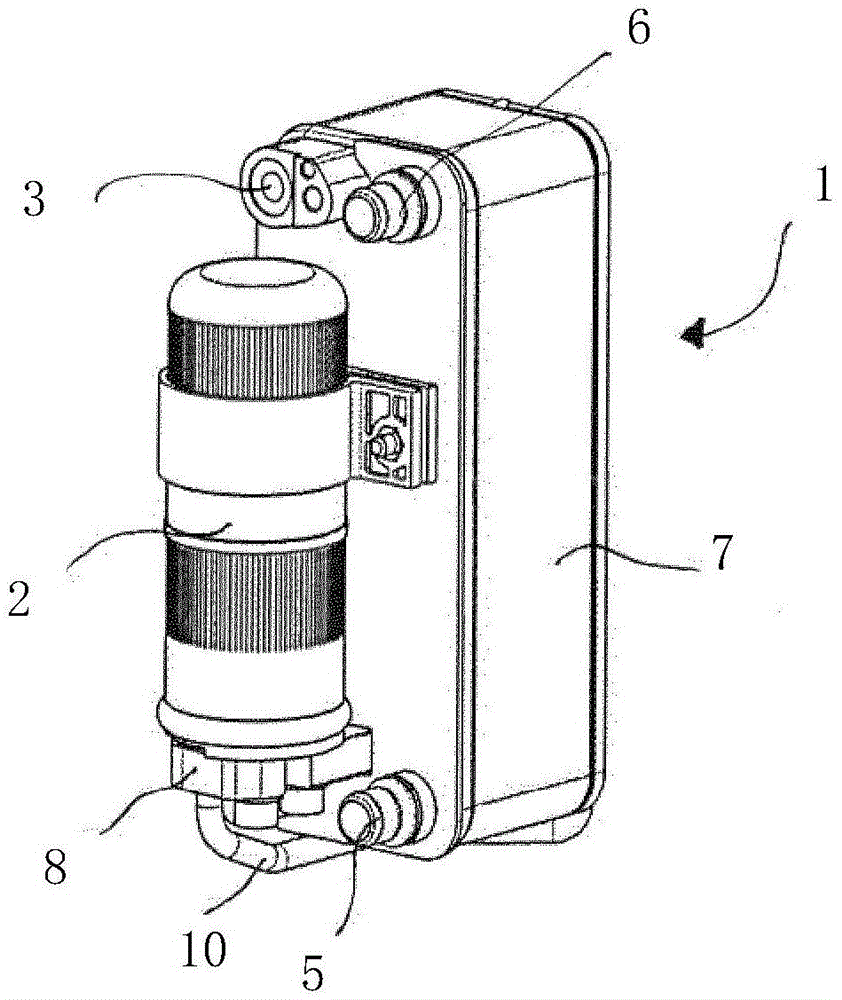
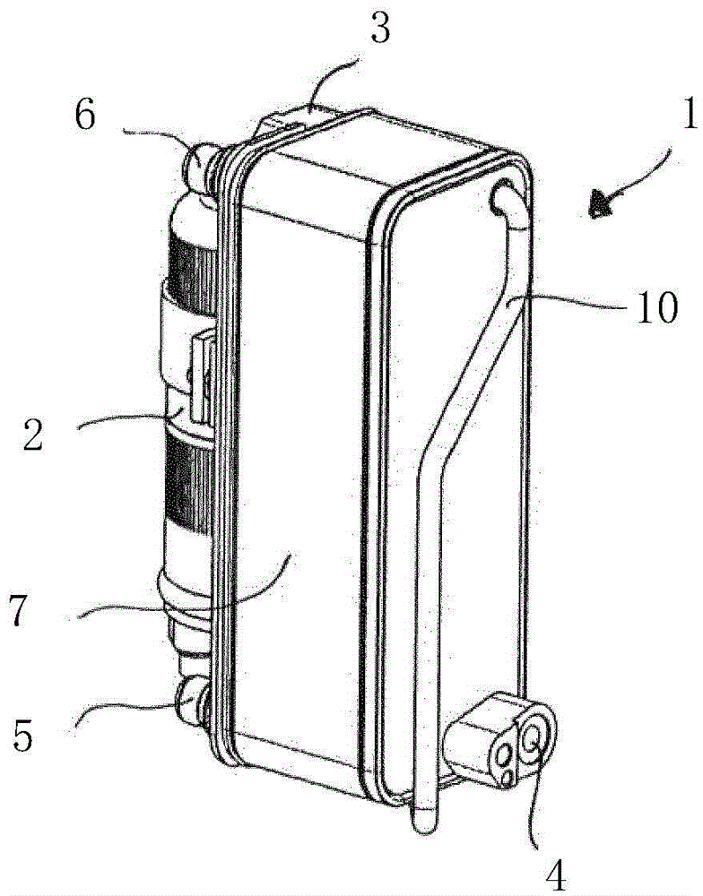
[0051] figure 1 A perspective view of the condenser 1 with stacked plate structure is shown. The condenser 1 is formed here from a plurality of individual plate elements which are stacked on top of each other to form a heat exchanger module 7 . The heat exchanger module 7 is designed in such a way that a plurality of channels are produced between the individual plate elements. Some channels are assigned to first flow channels through which refrigerant can flow. Other channels are assigned to second flow channels through which coolant can flow. Inside the heat exchanger module 7, the first flow channel is at least partially in thermal contact with the second flow channel, thus enabling heat transfer between the first flow channel and the second flow channel.

[0052] Through various configurations of the plate elements, a plurality of flow paths for the first and second flow channels can be formed within the interior of the heat exchanger module 7 . The fluid flowing throug...


PUM


Abstract

The invention relates to a condenser (1, 20, 40, 60) of stacked plate structure, wherein a heat exchanger module (7, 22, 42, 62) is formed by a plurality of plate elements, when these plate elements are stacked on top of each other, Mutually adjacent channels are formed between them, wherein a first number of channels is assigned to the first flow channel, a second number of channels is assigned to the second flow channel, and the refrigerant can flow through the first flow channel, the coolant able to flow through a second flow channel, wherein the first flow channel has a first region (34, 54, 81) for cooling and condensing the vaporous refrigerant and a second region for supercooling the condensed refrigerant. Two zones (35, 55, 82) in which at least one section of the first flow channel is in thermal contact with at least one section of the second flow channel and the first zone has a first fluid supply line (23, 43, 63) and a first fluid discharge line (24, 44, 64), the second area has a second fluid supply line (25, 45, 65) and a second fluid discharge line (26, 46, 66) , wherein the condenser (1, 20, 40, 60) has a collector (2, 21, 41, 61) for storing refrigerant, and the refrigerant passes through the collector (2, 21, 41, 61) from the first One area overflows to a second area, wherein the collector (2, 21, 41, 61) passes through a first fluid discharge line (24, 44, 64 is in fluid communication with the first zone and is in fluid communication with the second zone through a second fluid supply line (25, 45, 65) also constituting the fluid outlet of the collector (2, 21, 41, 61) , wherein the collector (2, 21, 41, 61) is arranged on the outer surface of the condenser (1, 20, 40, 60).

Description

technical field [0001] The invention relates to a condenser with a stacked plate structure, wherein the heat exchanger module is composed of a plurality of plate elements, and channels adjacent to each other are formed between these stacked plate elements, wherein the first number of channels belongs to the first flow passages, the second number of passages are assigned to the second flow passages, and the refrigerant can flow through the first flow passages, the coolant can flow through the second flow passages, wherein the first flow passages have a function for cooling the vapor refrigerant and a first zone for condensation, and a second zone for supercooling the condensed refrigerant. Background technique [0002] Condensers are used in the refrigerant circuit of motor vehicle air conditioning systems in order to cool the refrigerant to a condensation temperature and subsequently condense the refrigerant. Condensers usually have a collector in which a certain refrigeran...

Claims


Application Information

Patent Timeline
Patent Type & Authority Patents(China)
IPC IPC(8): F25B39/04F28D9/00F28F9/26F28D21/00
CPCF25B39/04F28D9/0056F28D9/0075F28F9/26F25B2339/043F25B2339/044F28F2270/00F28D2021/0084F28D9/00
Inventor 赫伯特·霍夫曼斯特凡·斯米盖尔萨沙·安格
Owner MAHLE INT GMBH
Why Eureka
Try Eureka