Wheel carrier for multi-link axles for mounting on a motor vehicle

A multi-link, motor vehicle technology, applied in the direction of the cantilever, suspension, and vehicle parts installed on the pivot, can solve the problems of expensive manufacturing technology, improve the degree of freedom of modeling, reduce manufacturing costs, and high molding freedom degree of effect

Active Publication Date: 2017-04-05
BENTELER AUTOMOBILTECHNIK GMBH
View PDF1 Cites 0 Cited by
  • Summary
  • Abstract
  • Description
  • Claims
  • Application Information

AI Technical Summary

Problems solved by technology

[0007] However, multi-link shafts of this type are structurally and technically expensive compared to simpler shaft designs such as composite link shafts.

Method used


Image

  • Wheel carrier for multi-link axles for mounting on a motor vehicle
  • Wheel carrier for multi-link axles for mounting on a motor vehicle
  • Wheel carrier for multi-link axles for mounting on a motor vehicle

Examples


Embodiment Construction

[0033] In the drawings, the same reference numerals are used for the same or similar components even when repeated description is omitted for the sake of simplification.

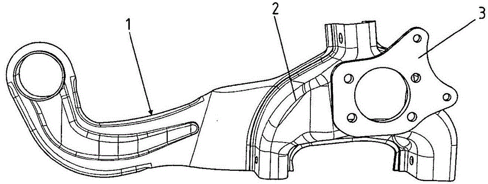
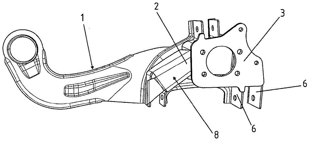
[0034] figure 1 A longitudinal link 1 and a wheel carrier 2 welded to the longitudinal link 1 are shown, wherein the wheel carrier 2 is formed as a single-shell profiled sheet metal component. Together with the wheel carrier 2 itself, a flange 3 in the form of a flange plate is again shown for coupling to a not further shown hub.

[0035] The wheel carrier 2 itself is coupled materially to the longitudinal link 1 by means of a welded connection, not shown further.

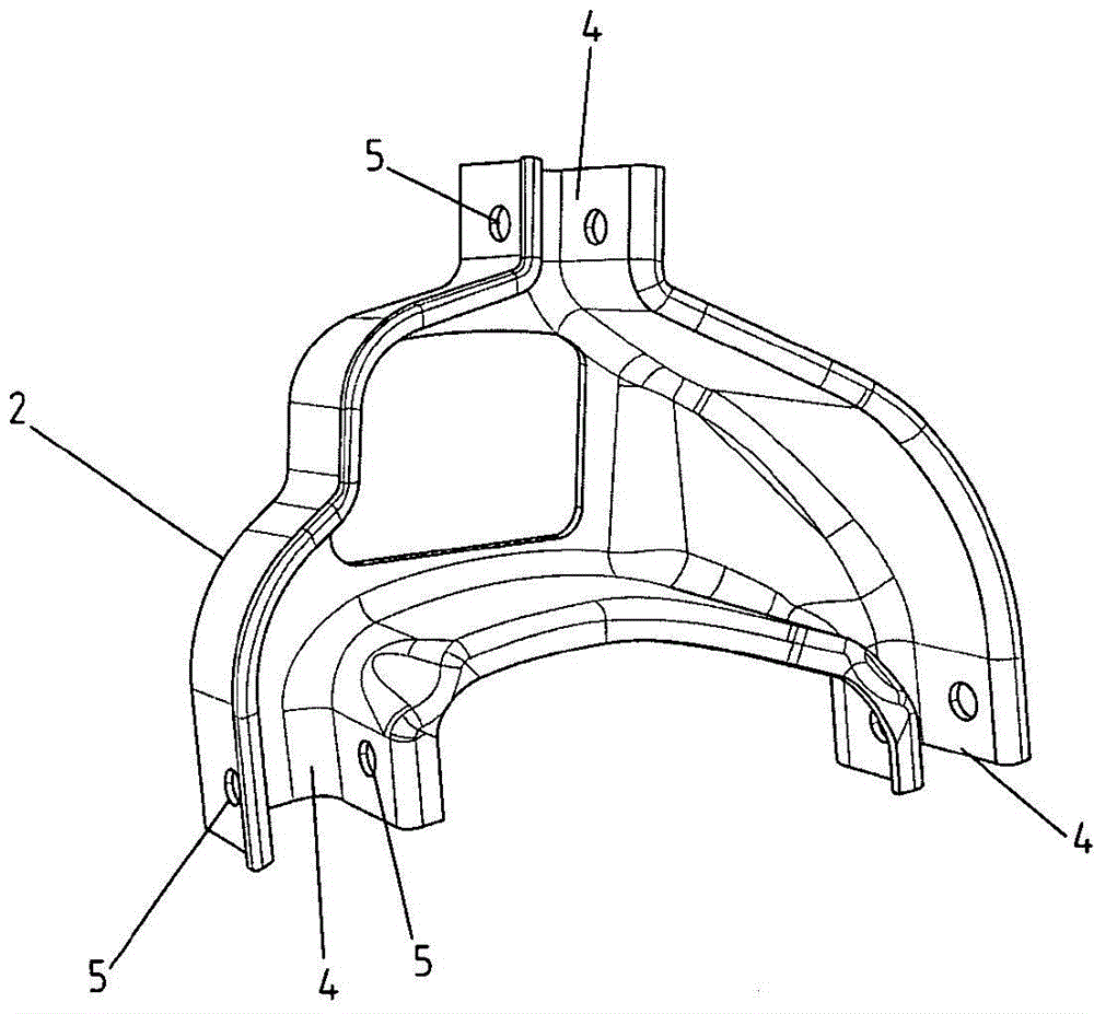
[0036] figure 2 The rear side of a wheel carrier 2 known from the prior art is shown, wherein three receptacles 4 are clearly formed, wherein a mounting opening is formed on each receptacle 4 on the left and on the right 5 serves to accommodate bolts, not further shown, so that a connecting rod, likewise not further shown, can be rotatably coup...


PUM


Abstract

The invention relates to a wheel carrier (2) for mounting on a motor vehicle axle, in particular a multi-link axle, which wheel carrier has a flange (3) for accommodating a wheel hub and for connecting with a connecting rod. Rotatably coupled at least two receptacles (4), wherein the wheel carrier (2) is thermally coupled to the longitudinal link (1), characterized in that the wheel carrier (2) is designed as a welded component and has A base body region (10) with at least two plate components, which are coupled to one another by thermal bonding.

Description

technical field [0001] The invention relates to a wheel carrier for the construction of a multi-link axle for arrangement on a motor vehicle. Background technique [0002] The motor vehicle has a wheel suspension in order to produce a kinematic coupling with the motor vehicle wheel, so that the motor vehicle wheel can move relative to the motor vehicle body and can be elastically compressed or elastically expanded. [0003] The aim here is a non-sprung wheel mass, so that the wheel-side components are designed to be as light as possible in order to achieve a high degree of flexibility and dynamics in terms of the driving behavior of the motor vehicle. [0004] At the same time, predetermined geometrical dimensions must be observed in order to obtain the required geometrical freedom in the region of the construction space so that the shaft structural parts do not collide during elastic compression and expansion. [0005] For this purpose, independent suspensions with a multi...

Claims


Application Information

Patent Timeline
Patent Type & Authority Patents(China)
IPC IPC(8): B60G7/00
CPCB60G3/202B60G7/008B60G2200/182B60G2206/50B60G2206/722B60G2206/82013B23K1/00F16F1/3686B60G7/001
Inventor D·派茨
Owner BENTELER AUTOMOBILTECHNIK GMBH
Why Eureka
Try Eureka