
Navigation apparatus

A technology for navigation devices and battery life, applied in navigation, electrical devices, measuring devices, etc., can solve problems such as increased psychological burden on users, increased burden, and inability to use users

Inactive Publication Date: 2015-05-13
DENSO CORP
View PDF9 Cites 12 Cited by
  • Summary
  • Abstract
  • Description
  • Claims
  • Application Information

AI Technical Summary

Problems solved by technology

The user has to perform an operation for storing the boundary of the drivable range on the screen.
In addition, since the electronic map is automatically changed to the largest scale that can display the non-display boundary corresponding to the frame selected by the user, it becomes a low scale when the drivable range is wide, and a small scale when the drivable range is narrow. High scale, unable to use the user's preferred scale to display the electronic map
[0007] In addition, in the case of displaying the drivable range centered on the position of the own vehicle as a circular shape corresponding to the actual distance on the electronic map like the technology disclosed in Patent Document 1, there is a possibility that the user's psychological burden will become larger. big problem
Specifically, when the drivable range is displayed as described above, since the display is performed in all directions 360 degrees from the position of the own vehicle, the burden on the user to determine in which direction the cruising distance can be obtained becomes large.
[0008] On the other hand, if the display showing the drivable range is narrowed down to only the guidance route to the destination like the technique disclosed in Patent Document 2, the user's judgment as to which direction to go to gain the cruising distance can be alleviated. burden, but cannot respond when the own vehicle deviates from the guidance path
Therefore, the route traveled by the electric vehicle is restricted, and there is a problem of lack of convenience for the user.

Method used


Image

  • Navigation apparatus
  • Navigation apparatus
  • Navigation apparatus

Examples


Embodiment Construction

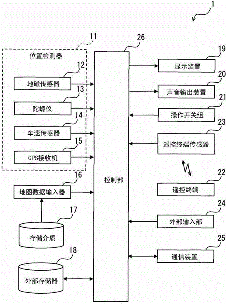
[0027] Embodiments of the present application will be described below using the drawings. figure 1 The illustrated navigation device 1 is mounted on an electric vehicle and has navigation functions such as route search and route guidance. An electric vehicle is an electric vehicle (EV) that uses only an electric motor (motor) as a drive source for travel, and has a structure capable of charging a travel battery that supplies power to the motor by receiving power supply from outside the vehicle. In addition, it is also possible to adopt a configuration in which the present application is applied to a plug-in hybrid vehicle (PHV) in which a motor and an engine are used together as driving sources for travel.

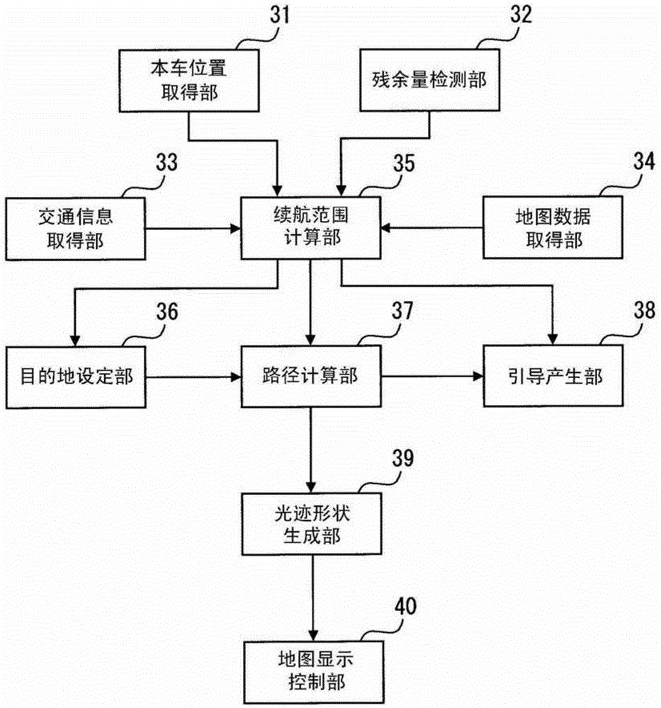
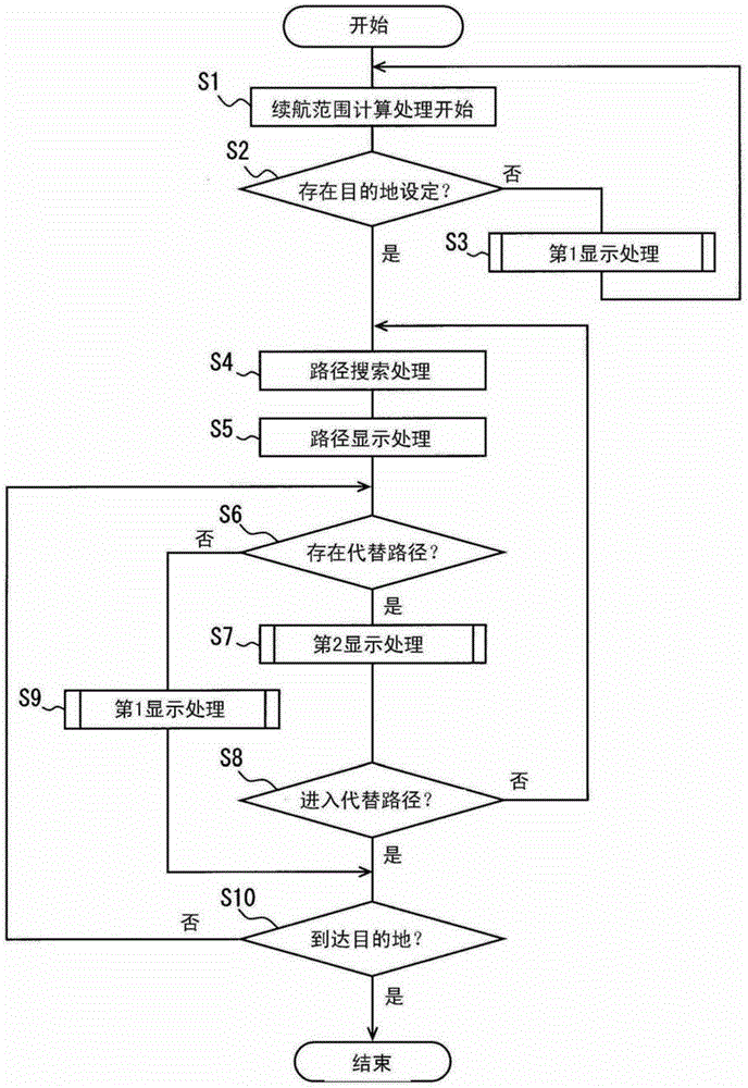
[0028] Such as figure 1 As shown, the navigation device 1 includes: a position detector (POSI DETC) 11, a map data input device (M-DATA IN) 16, a storage medium (STORAGE) 17, an external memory (EXT MEMORY) 18, and a display device (DISPLAY) 19 , sound output device (AUD...


PUM


Abstract

A navigation apparatus utilized in an electric vehicle includes a position obtaining section subsequently obtaining present position of the electric vehicle, a display controller displaying an electronic map on a display device, an available travel range calculation section, an estimation available travel range calculation section, and a progress calculation section calculating progress of the available travel range relative to the estimation available travel range. The available travel range is available travel distance or available travel time that can be traveled with remaining power of the travelling battery. The display controller displays light beam locus having sector-like shape on the electronic map with the present position as a base in a travelling direction, and changes a length of the light beam locus in the travelling direction corresponding to progress of the available travel range under a condition that the light beam locus is entirely displayed on the display device.

Description

[0001] This application is based on Japanese application number 2012-172228 for which it applied on August 2, 2012, and uses the description content here. technical field [0002] The present application relates to navigation devices for use in electric vehicles. Background technique [0003] Conventionally, there is known a navigation device that displays a cruising range of an electric vehicle on an electronic map. [0004] For example, Patent Document 1 discloses a technique of displaying a cruising range of an electric vehicle by displaying the cruising range of the electric vehicle on an electronic map in a circular shape centered on the own vehicle. In the technique disclosed in Patent Document 1, when the entire boundary of the travelable range of the electric vehicle is not accommodated in the display area (that is, the screen) of the display, a frame or the like is displayed to specify the position of the non-display boundary. Furthermore, when the user selects the...

Claims


Application Information

Patent Timeline
Patent Type & Authority Applications(China)
IPC IPC(8): G01C21/34B60L3/00G09B29/00G09B29/10
CPCB60L1/003B60L3/12B60L7/12B60L2200/10B60L2240/12B60L2240/34B60L2240/622B60L2240/80B60L2250/10B60L2250/16B60L2260/52B60L2260/54B60L50/52G01C21/3469G01C21/3667G01C21/3697G09B29/106B60L58/12G09B29/007Y02T10/70Y02T10/72Y02T90/16
Inventor 久保俊逸
Owner DENSO CORP
Learn More