Deep scarification cultivation machine auger bit of preventing soil mounding

A technology of auger bit and cultivator, which is applied in the direction of agricultural machinery and implements, application, plow, etc., can solve the problems of piling up soil and reducing the production efficiency of arable land operations, and achieve the effects of improving production efficiency, simple structure, and eliminating the phenomenon of piling up soil

Inactive Publication Date: 2015-05-20
GUANGXI WUFENG MACHINERY CO LTD
View PDF13 Cites 13 Cited by
  • Summary
  • Abstract
  • Description
  • Claims
  • Application Information

AI Technical Summary

Problems solved by technology

The above-mentioned rotary grinding type deep plowing powder ridge multifunctional machine, its auger drill rod must be connected with the rotary grinder bit device, however, when the auger is working on the land, the auger rod moves forward while rotating, and it is easy to generate piles in front of the auger rod. Soil phenomenon, which reduces the productivity of arable land operations

Method used


Image

  • Deep scarification cultivation machine auger bit of preventing soil mounding
  • Deep scarification cultivation machine auger bit of preventing soil mounding

Examples


Embodiment 1

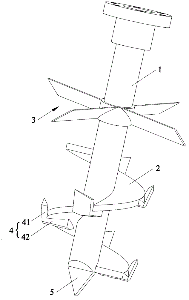
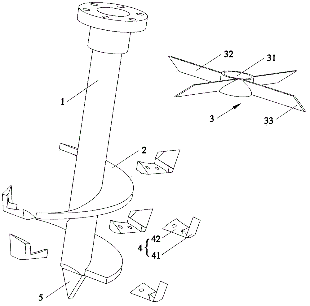
[0022] Such as figure 1 , figure 2 As shown, the direction of this embodiment is figure 1 The placement direction of the auger bit of the subsoil cultivator that avoids piled up soil as shown is as the criterion, and the auger bit of a subsoil tiller that avoids piled up soil in this embodiment includes a drill rod 11, a helical blade 2, and a helical blade 2 is wound around the lower part of the drill rod 1, and it also includes a cross-cutting blade 3, which is arranged on the upper part of the drill rod 1 and above the helical blade 2. The structure of the present invention is simple, because the upper part of the drill pipe 1 is provided with a cross-cutting blade 3, the cross-cutting blade 3 can be connected to the upper half of the drill pipe 1 by welding or fasteners, and the drill pipe 1 rotates while working on the land. As the subsoiling tiller moves forward, the cross-cutting blade 3 can effectively level the piled soil generated in front of the drill pipe 1 afte...

Embodiment 2

[0028] The difference between this embodiment and the first embodiment is that in this embodiment, the auger bit further includes a soil cutting blade 4 , which is arranged on the peripheral edge of the helical blade 2 . When using the auger bit of the present invention to plow the land, the helical blade 2 rotates to ridge up the soil, and the soil cutting blade 4 can assist the helical blade 2 to cut, rub and pulverize the soil that is automatically ridged upward by the action of the helical blade 2, greatly The efficiency of cutting the soil layer of the auger bit and the working efficiency of the subsoiler are improved, and it is also beneficial to store more air inside the soil.

[0029] In this embodiment, there are at least two soil cutting blades 4 , and at least two soil cutting blades 4 are arranged at intervals along the helical direction of the helical blade 2 . The more the number of soil cutting blades 4 is, the more beneficial the auxiliary helical blades 2 are ...


PUM


Abstract

The invention relates to the technical field of drill bits, in particular to a deep scarification cultivation machine auger bit preventing soil mounding. The auger bit comprises a drill rod, a spiral blade and horizontal cutting blades, wherein the spiral blade is wound around the lower portion of the drill rod, and the horizontal cutting blades are arranged on the upper portion of the drill rod and located above the spiral blade. The auger bit is simple in structure, due to the fact that the horizontal cutting blades are arranged on the upper portion of the drill rod and can be welded or connected to the upper half portion of the drill rod through fasteners, in plough operation, the drill rod rotates while moving forwards along with the deep scarification cultivation machine, the horizontal cutting blades can effectively flatten the soil mound generated in front of the drill rod after deep scarification, the soil mounding phenomenon is eliminated, and production efficiency of plough operation is greatly improved.

Description

technical field [0001] The invention relates to the technical field of drill bits, in particular to an auger bit for a subsoiling cultivator which avoids piling up soil. Background technique [0002] The main function of tillage equipment is to deep plow and deep loosen the land. In the past, the deep plow subsoiler used the tractor as the platform, and used the old traditions such as plowing, beating, and harrowing. The cultivation time is short and the cultivation depth is shallow, which is not conducive to agricultural production. Therefore, for large areas of land that require deep plowing and deep loosening, the traditional method has been unable to adapt. For this reason, the current automated deep plowing and deep loosening have emerged. [0003] The Chinese utility model patent application with the application number 201020514808.9 discloses a rotary grinding type deep plowing powder ridge multifunctional machine, and specifically discloses that it includes an engin...

Claims


Application Information

Patent Timeline
Patent Type & Authority Applications(China)
IPC IPC(8): A01B13/08
Inventor 李阳铭
Owner GUANGXI WUFENG MACHINERY CO LTD
Why Eureka
Try Eureka