
Pipe punching die

A mold and pipe technology, applied in the direction of perforating tools, manufacturing tools, feeding devices, etc., can solve the problems of increasing mold assembly time, easily causing industrial accidents, pipe deviation, etc., to reduce mold structure and weight, save materials and Manpower, the effect of improving the life of the die

Active Publication Date: 2017-10-13
GUANGXI YANGSHI ELECTROMECHANICAL TECH
View PDF7 Cites 0 Cited by
  • Summary
  • Abstract
  • Description
  • Claims
  • Application Information

AI Technical Summary

Problems solved by technology

[0002] Existing stamping dies include bottom die, punching pin, guide post and middle die. The punching pin is installed on the punch head and needs guide post to guide the punching pin into the bottom die. Mold assembly time, loading and unloading the mold is slow and time-consuming; at the same time, the punching needle leaves the top of the bottom mold when it is in the working state, which may easily cause industrial accidents; the inner wall of the mold is completely in contact with the pipe during stamping.
In addition, because there is no limit device on the left, right, front and back of the pipe during punching, it is easy to cause the pipe to shift during the punching process and affect the punching accuracy

Method used

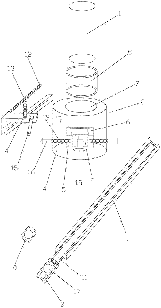

Image

  • Pipe punching die

Examples


Embodiment Construction

[0022] The following will clearly and completely describe the technical solutions in the embodiments of the present invention with reference to the accompanying drawings in the embodiments of the present invention. Obviously, the described embodiments are only some, not all, embodiments of the present invention. Based on the embodiments of the present invention, all other embodiments obtained by persons of ordinary skill in the art without creative efforts fall within the protection scope of the present invention.

[0023] see figure 1 As shown, the present invention provides a pipe punching die, including a punching needle 1, a mold body 2 and a middle mold 3, the lower end of the mold body 2 is provided with a bottom mold 4, and the middle part of the bottom mold 4 is hollowed out to form a mold cavity 5. The upper end of the mold cavity 5 is provided with a positioning block 6 with a through hole, the middle mold 3 can be inserted into the mold cavity 5, the upper end of th...


PUM


Abstract

The invention relates to the technical field of punching dies, in particular to a pipe punching die. According to the technical scheme, the pipe punching die comprises a punching needle, a die body and a middle die. A bottom die is arranged at the lower end of the die body, and the middle of the bottom die is hollowed out to form a die cavity. A positioning block with a through hole is arranged at the upper end in the die cavity, and the middle die can be inserted in the die cavity. A pin hole is formed in the upper end of the bottom die, and a punching pin sleeve which is used for directly leading a punching pin to work is arranged in the pin hole in a sleeved mode. The pin punching sleeve and the pin hole are arranged in a separable mode, and the punching pin can be arranged in the punching pin sleeve in a sleeved mode to make axial movement. The pipe punching die has the advantages that a guide column is of no need, a pipe is stably fixed, and the punching precision is high.

Description

technical field [0001] The invention relates to the technical field of punching dies, in particular to a pipe punching die. Background technique [0002] Existing stamping dies include bottom die, punching pin, guide post and middle die. The punching pin is installed on the punch head and needs guide post to guide the punching pin into the bottom die. Mold assembly time, loading and unloading the mold is slow and time-consuming; at the same time, the punching needle leaves the top of the bottom mold when it is in the working state, which may easily cause industrial accidents; the inner wall of the mold is completely in contact with the pipe during stamping. In addition, since there is no limit device on the left, right, front and back of the pipe during punching, it is easy to cause the pipe to shift during the punching process and affect the punching accuracy. Contents of the invention [0003] In order to solve the above-mentioned existing technical shortcomings, the pr...

Claims


Application Information

Patent Timeline
Patent Type & Authority Patents(China)
IPC IPC(8): B21D28/34B21D28/28
CPCB21C51/00B21D28/28B21D28/34B21D43/003
Inventor 李国扬
Owner GUANGXI YANGSHI ELECTROMECHANICAL TECH
Learn More