Mechanical arm joint quick changing port capable of being replaced on track

A technology of manipulator and interface replacement, which is applied in the field of aerospace, can solve the problems of large-scale space manipulators, in-orbit maintenance, etc., and achieve the effect of large tolerance capability, low tolerance requirements, and reliable locking

Active Publication Date: 2015-05-20
HARBIN INST OF TECH
View PDF7 Cites 8 Cited by
  • Summary
  • Abstract
  • Description
  • Claims
  • Application Information

AI Technical Summary

Problems solved by technology

[0005] In order to solve the problem that the existing large-scale space manipulator cannot be maintained on the track, the present invention further proposes a quick-change interface of the manipulator joint that can be replaced on the track

Method used


Image

  • Mechanical arm joint quick changing port capable of being replaced on track
  • Mechanical arm joint quick changing port capable of being replaced on track
  • Mechanical arm joint quick changing port capable of being replaced on track

Examples


specific Embodiment approach 1

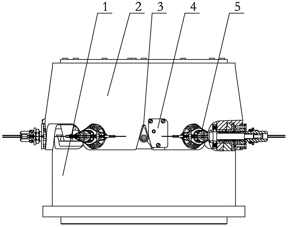
[0009] Specific implementation mode one: combine Figure 1 to Figure 10 Describe the present embodiment. The on-rail replaceable mechanical arm joint quick-change interface described in this embodiment includes a convex body 1, a concave body 2 matching with the convex body, a guide mechanism 3, a positioning mechanism 4, an electrical connector auxiliary The connection mechanism and six quick-disconnect connection mechanisms 5, the positioning mechanism 4, and the auxiliary connection mechanism of the electrical connector are installed on the concave body 2, the guide mechanism 3 is installed on the convex body 1, and the six quick-disconnect connection mechanisms 5 are installed evenly On the female body 2 , the female body 2 is connected to the male body 1 through six quick-disconnect connection mechanisms 5 .

specific Embodiment approach 2

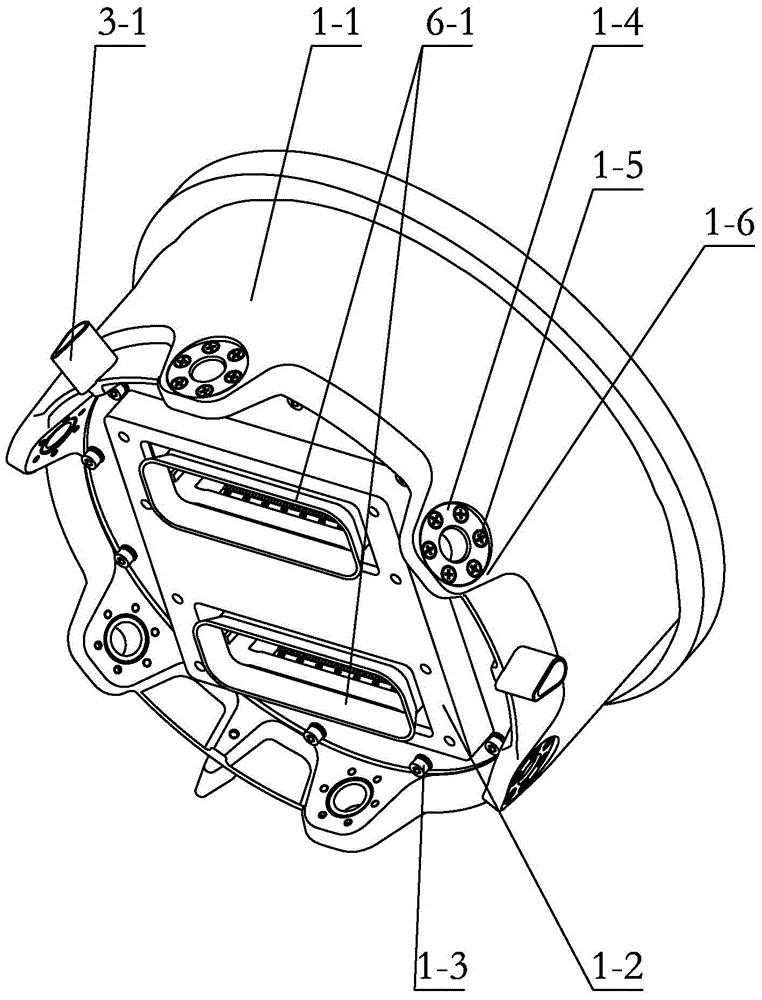
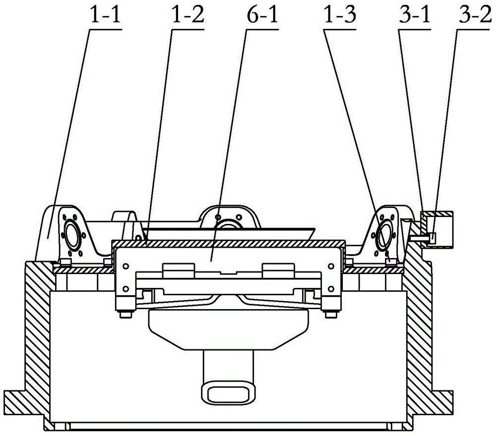
[0010] Specific implementation mode two: combination Figure 1 to Figure 4 Describe this embodiment, the convex body 1 of the on-rail replaceable mechanical arm joint quick-change interface described in this embodiment includes a convex body shell 1-1, a first electrical connector positioning plate 1-2, and six expansion pins Set 1-4, a plurality of first connecting screws 1-3 and a plurality of second connecting screws 1-5, the first electrical connector positioning plate 1-2 is installed side by side on the convex body through a plurality of first connecting screws 1-3 Inside the casing 1-1, six lugs 1-6 are evenly distributed along the circumferential direction on the lower surface of the convex body casing 1-1, and each lug 1-6 is respectively inserted with an expansion pin sleeve 1-4, each Each expansion pin sleeve 1-4 is fixedly connected with the lug 1-6 through a plurality of second connecting screws 1-5.

[0011] The technical effect of this embodiment is: such arran...

specific Embodiment approach 3

[0012] Specific implementation mode three: combination Figure 5 and Figure 6 Describe this embodiment. The concave body 2 of the on-rail replaceable mechanical arm joint quick-change interface in this embodiment includes a concave body shell 2-1, a bottom plate 2-7, and six outer ring expansion pin sleeves 2-3. , six inner ring expansion pin sleeves 2-5, a plurality of third connecting screws 2-2, a plurality of fourth connecting screws 2-4 and a plurality of fifth connecting screws 2-8, the outer shell of the concave body shell 2-1 Six outer ear plates 2-1-1 are evenly distributed along the circumferential direction on the ring, and six inner ear plates 2-1-2 are evenly distributed along the circumferential direction on the inner ring of the concave body shell 2-1, and each outer ear plate 2- 1-1 and an inner ear plate 2-1-2 form a pair of locking ear plates, each lug 1-6 on the convex body 1 can be inserted into a pair of said locking ear plates correspondingly, each oute...


PUM


Abstract

The invention relates to a mechanical arm joint quick changing port, in particular to a mechanical arm joint quick changing port capable of being replaced on a track. The mechanical arm joint quick changing port aims at solving the problem that an existing large space mechanical arm cannot conduct maintenance on the track. The mechanical arm joint quick changing port comprises a convex body, a concave body matched with the convex body, a guiding mechanism, a positioning mechanism, an electric connector auxiliary connecting mechanism and six quick detaching and connecting mechanisms, wherein the positioning mechanism and the electric connector auxiliary connecting mechanism are installed on the concave body, the guiding mechanism is installed on the convex body, the six quick detaching and connecting mechanisms are evenly installed on the concave body, and the concave body is connected with the convex body through the six quick detaching and connecting mechanisms. The mechanical arm joint quick changing port is suitable for the aerospace field.

Description

technical field [0001] The invention relates to a quick-change interface of a mechanical arm joint, in particular to a quick-change interface of a mechanical arm joint that can be replaced on rail, and belongs to the field of aerospace. Background technique [0002] The large space robotic arm is an indispensable operating tool for the space station, which can minimize the high-risk and high-cost outbound operations of astronauts. The space manipulator is a supporting technology for on-orbit maintenance and construction. Through remote operation on the ground or autonomous operation of the manipulator, it can achieve precise positioning, grasp, transport, and replace objects, and realize orbit maintenance operations and space station assembly tasks. It can cooperate with astronauts to go out of the warehouse to carry out difficult maintenance tasks. Large space manipulators are characterized by high cost, complex structure and long-term on-orbit operation. At present, the ...

Claims


Application Information

Patent Timeline
Patent Type & Authority Applications(China)
IPC IPC(8): B25J17/00
Inventor 史士财何阳阮思朴王达李荣刘宏
Owner HARBIN INST OF TECH
Why Eureka
Try Eureka