Light guide plate scribing machine and cutting die device thereof

A technology of light guide plate and cutting die, which is applied in metal processing and other directions, can solve the problems of difficulty in achieving uniformity and depth of scribing lines, high power consumption, and low efficiency, so as to reduce equipment costs and processing power consumption, and improve Processing efficiency, consistent depth effect

Inactive Publication Date: 2015-05-20
DONGGUAN FALA CNC EQUIP
View PDF8 Cites 6 Cited by
  • Summary
  • Abstract
  • Description
  • Claims
  • Application Information

AI Technical Summary

Problems solved by technology

[0003] If the traditional cutting die is used for the engraved line processing of the light guide plate, because the uniformity and depth of the engraved lines are difficult to achieve consistency, and the flatness of the light guide plate is very high, it basically cannot meet the production and application requirements.
At present, the dots of the light guide plate on the market are processed by laser engraving, which can achieve uniform processing of the dots of the light guide plate; however, when l

Method used


Image

  • Light guide plate scribing machine and cutting die device thereof
  • Light guide plate scribing machine and cutting die device thereof
  • Light guide plate scribing machine and cutting die device thereof

Examples


Embodiment Construction

[0019] The utility model relates to a light guide plate marking machine, which is used to carry out network dot marking on the light guide plate, and includes a numerical control device, a moving shaft and a cutting die device.

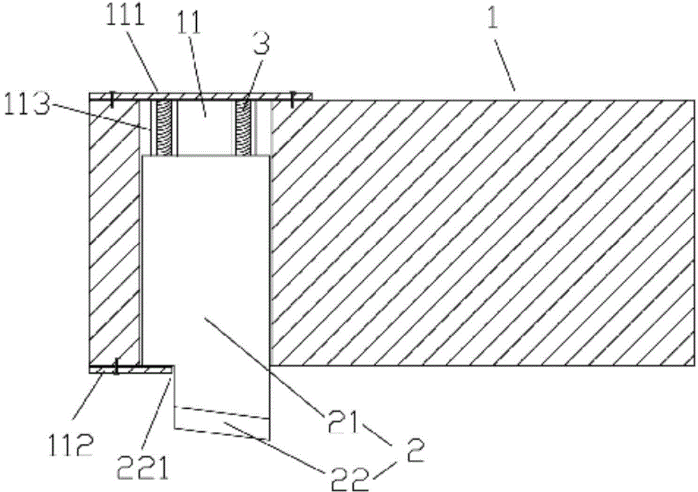
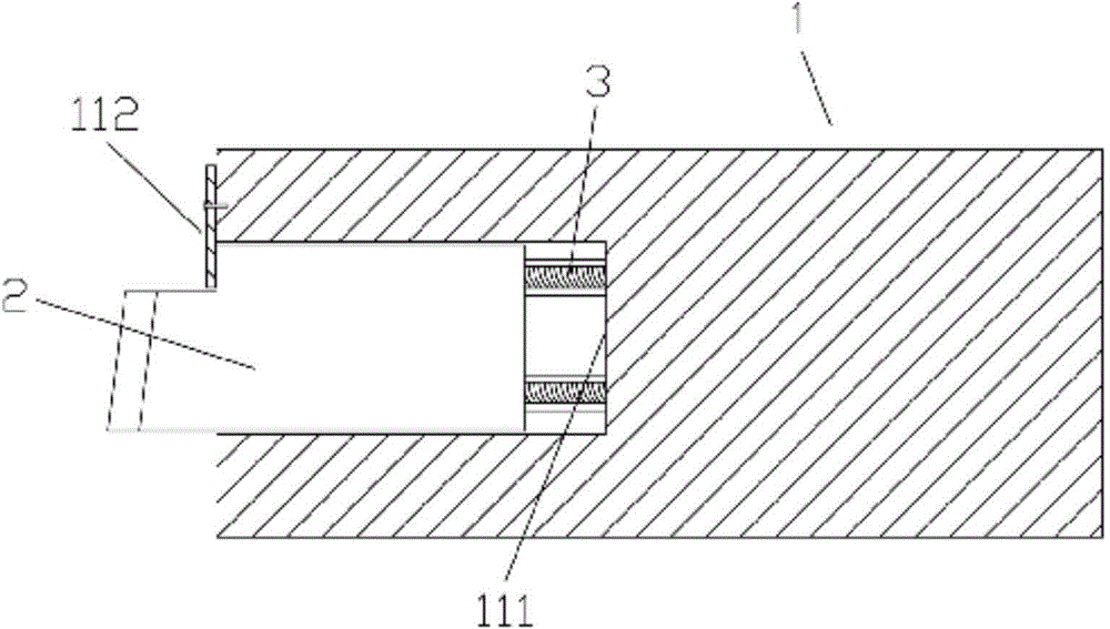
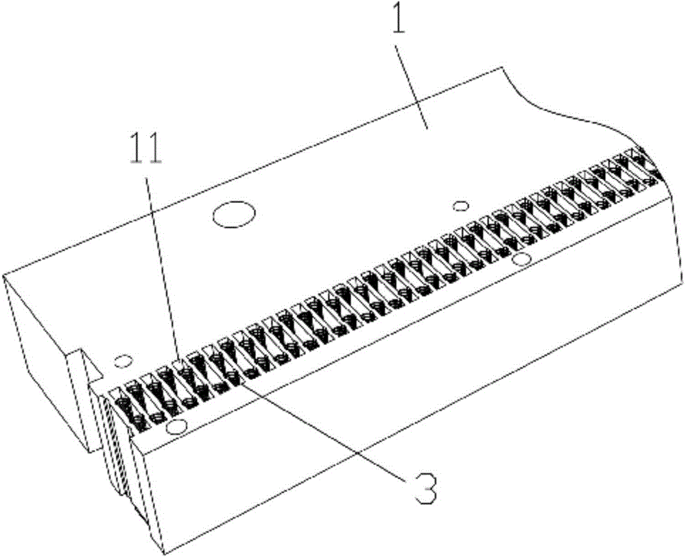
[0020] refer to Figure 1 to Figure 3 , The knife mold device includes a knife mold body 1 , a blade 2 , and an elastic member 3 .

[0021] There are several sipes 11 arranged side by side on the die die body 1, one end of the sipes 11 is a limiter 111, and a stopper 112 is also provided on the sipes 11; two kinds of sipes 11 are provided. In a preferred manner, when the sipes 11 are vertically penetratingly arranged on the die die body 1 , the limiting end 111 of the sipes 11 is a limit top plate fixed on the top surface of the die die body 1 ; When the knife groove 11 is arranged laterally on the knife mold body 1 , the limiting end 111 of the knife groove 11 is a closed end.

[0022] The blade 2 includes a blade body 21 and a knife edge 22 connec...


PUM


Abstract

The invention discloses a light guide plate scribing machine and a cutting die device of the light guide plate scribing machine. The cutting die device is technically characterized by comprising a cutting die body, blades and elastic components; the cutting die body is provided with a plurality of cutter grooves formed in parallel, one end of each cutter groove is a limiting end, and each cutter groove is further provided with a limiting part; each blade comprises a blade body and a cutting edge connected to the bottom end of the blade body, wherein the blade is inserted into the corresponding cutter groove in a clearance fit mode, and the cutting edge extends out of the corresponding cutter groove; the elastic components are clamped between the blades and the limiting ends of the corresponding cutter grooves, the blades can slide along the corresponding cutter grooves under the action of elastic force of the elastic components, and the limiting parts limit the positions, sliding out of the corresponding cutter grooves, of the corresponding blades. Even if a plate is uneven, the extension length of the blades can be adjusted through the elastic components, and the consistency of scribing depths is guaranteed; the blades are free of swinging by adjusting fit tolerance, and the scribing uniformity can be guaranteed; by means of modularized connection of the cutting die device, lines can be quickly scribed in plates with different areas, and efficiency is very high; compared with a laser scribing device, the cutting die device has the advantage that the equipment cost and power consumption of machining are greatly reduced.

Description

technical field [0001] The invention relates to the technical field of light guide plate scribe line processing equipment, in particular to a light guide plate scribe line machine and a cutting die device thereof. Background technique [0002] As the light guide plate is more and more widely used in various industries, the production technology of the light guide plate is also constantly improving. The processed light guide plate has the advantages of high brightness, not easy to yellow, durable, etc., which is far better than the processing effect of printing. [0003] If the traditional cutting die is used for the engraving process of the light guide plate, because the uniformity and depth of the engraved lines are difficult to achieve consistency, and the flatness of the light guide plate is very high, it basically fails to meet the production and application requirements. At present, the dots of the light guide plate on the market are processed by laser engraving, which...

Claims


Application Information

Patent Timeline
IPC IPC(8): B26D7/26B26D1/00
Inventor 黄小岳李鑫
Owner DONGGUAN FALA CNC EQUIP
Why Eureka
Try Eureka