Rotary type double-nozzle switching device for 3D printing

A 3D printing and switching device technology, applied in additive processing and other directions, can solve problems such as material, color error, affecting printing accuracy, workpiece deformation, etc., to reduce motor load, improve printing accuracy, and save costs.

Active Publication Date: 2015-05-20
JIANGSU HAOYU ELECTRONICS TECH
View PDF6 Cites 28 Cited by
  • Summary
  • Abstract
  • Description
  • Claims
  • Application Information

AI Technical Summary

Problems solved by technology

[0006] 4. The nozzles are fixed and installed side by side. Since the height of each nozzle is the same, when one of the nozzles is moved to the position where it needs to work, other non-working nozzles can easily collide with the printed workpiece; one of the nozzles When working, it is also very easy to cause the non-working nozzle to collide with the uncured workpiece printed by the working nozzle, causing errors in materials and colors, and even deformation of the workpiece, which affects printing accuracy and affects the life of the nozzle

Method used


Image

  • Rotary type double-nozzle switching device for 3D printing
  • Rotary type double-nozzle switching device for 3D printing
  • Rotary type double-nozzle switching device for 3D printing

Examples


Embodiment 1

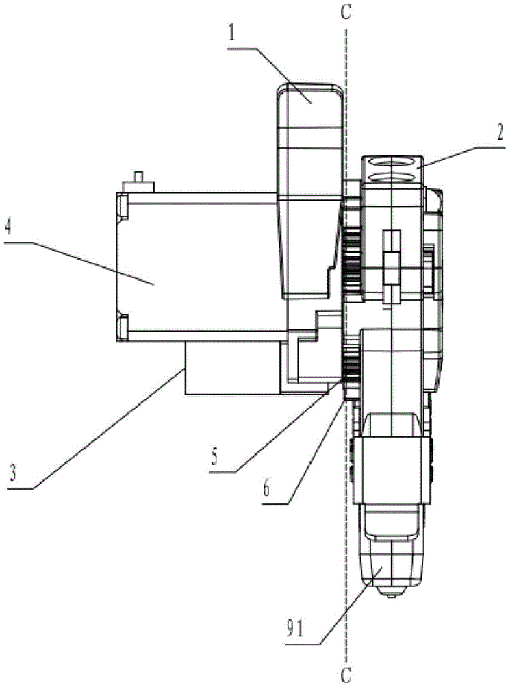
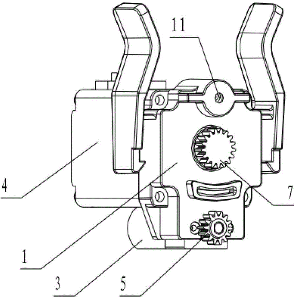
[0034] Example 1: Such as figure 1 , figure 2 , image 3 , Figure 5 , Figure 6 As shown, the rotary double nozzle switching device for 3D printing provided in Example 1 includes a first bracket 1, a second bracket 2, a steering motor 3, a steering gear 5, an arc rack 6, a wire feeding motor 4, and a wire feeding motor. driving wheel 7;

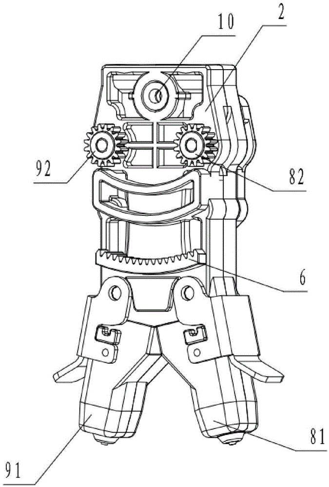
[0035] Such as figure 1 and figure 2 As shown, the steering motor 3 and the wire feeding motor 4 are fixedly arranged on the first bracket 1 . Such as image 3 As shown, the second bracket 2 is provided with a first nozzle installation groove and a second nozzle installation groove, and first and second wire feeding gears corresponding to the first and second nozzle installation grooves respectively (not shown in the figure output), and the first and second driven wheels coaxially connected with the first and second wire feeding gears respectively.

[0036] combine Figure 5 and Figure 6As shown, the second bracket 2 is rota...

Embodiment 2

[0044] Example 2: The structure is basically the same as that of Embodiment 1, and the similarities are no longer repeated, but the difference is:

[0045] The rotatable setting of the second bracket 2 on the first bracket 1 is realized in the following manner: the first bracket 1 is also fixedly provided with a rotation central axis; the curved rack 6 on the second bracket There is a perforation at the center of the circle, and a bearing in which the outer ring is in interference fit with the inner wall of the perforation; the inner ring of the bearing is in interference fit with the rotating central shaft.

[0046] The center of the arc formed by the first driven wheel 82 , the second driven wheel 92 and the center of the wire feeding driving wheel 7 (ie the arc center) coincides with the center of circle (ie the arc center) of the arc-shaped rack 6 .

[0047] Taking the preferred embodiment 1 as an example, using the 3D printing rotary double nozzle switching device provi...


PUM


Abstract

The invention discloses a rotary type double-nozzle switching device for 3D printing. The rotary type double-nozzle switching device comprises a steering motor and a wire feeding motor which are arranged on a first bracket; a second bracket is provided with a first nozzle mounting groove, a second nozzle mounting groove, a first wire feeding gear and a second wire feeding gear which correspond to the first nozzle mounting groove and the second nozzle mounting groove, and a first driven wheel and a second driven wheel which are coaxially connected with the first wire feeding gear and the second wire feeding gear; the second bracket is rotationally arranged on the first bracket; a steering gear is connected with the steering motor in a driving manner and is engaged with an arc-shaped rack on the second bracket; under the transmission of the steering gear, the arc-shaped rack enables the second bracket to swing on the first bracket by taking the circle center of the arc-shaped rack as the circle center; a wire feeding driving wheel is in driving connection with the wire feeding motor; when the second bracket swings to the right side, the second bracket is engaged with the first driven wheel; and when the second bracket swings to the left side, the second bracket is engaged with the second driven wheel. By virtue of the rotary type double-nozzle switching device for the 3D printing, the effective printing space is effectively improved when a 3D printer adopts double nozzles, and the mutual influences between the nozzles is higher; and the practicability is high and the usability is good.

Description

technical field [0001] The invention relates to a 3D printer component, in particular to a nozzle switching device on the 3D printer. Background technique [0002] When the multi-nozzle technology is used in existing 3D printers, each nozzle is controlled by an independent motor, and then fixed side by side with the same height to complete the 3D printing work. Such a multi-nozzle device has the following defects as a whole: [0003] 1. The overall nozzle is relatively heavy, which increases the motor load in two dimensions (X axis, Y axis) of 3D printing, which affects the printing accuracy to a certain extent; [0004] 2. The nozzle assembly is relatively large overall, and the design scheme of two nozzles fixed side by side at the same height reduces the effective printing space of a single nozzle on both sides of the X-axis; [0005] 3. There is a dead angle between the nozzles installed side by side and fixedly, which reduces the effective printing space; [0006] 4. ...

Claims


Application Information

Patent Timeline
Patent Type & Authority Applications(China)
IPC IPC(8): B29C67/00B33Y30/00
Inventor 魏宏辉魏天浩魏妗羽
Owner JIANGSU HAOYU ELECTRONICS TECH
Why Eureka
Try Eureka