A coupler buffer

A buffer and coupler technology, which is applied to railway car body parts, traction devices, transportation and packaging, etc., can solve the problems of the buffer effect of the coupler buffer, the difficulty of increasing the impact speed, and the large impact force, and achieve a good buffer effect. , The impact speed of the carriage is high, and the effect of improving stability and safety

Active Publication Date: 2017-04-05
ZHUZHOU TIMES NEW MATERIALS TECH
View PDF5 Cites 0 Cited by
  • Summary
  • Abstract
  • Description
  • Claims
  • Application Information

AI Technical Summary

Problems solved by technology

And in order to maintain the safety of the car connection and ensure that the traction impact between the couplers will not damage the couplers and the car body during the operation of the train, the force and stroke of the couplers used in trains with different structures are all limited by the maximum value. The maximum value will cause damage to the coupler and the car body and affect the safety performance of the connection between the car and the car. Constrained by the above restrictions and the stroke and resistance of the coupler buffer that is distributed along the central axis of the car, it is difficult to improve. The coupler buffer The improvement of the capacity of the coupler is also restricted. The energy absorbed by the coupler buffer is small during the stress process, and it is difficult to increase the impact speed of the carriage. Large, the impact speed of the carriage against the other carriage is very high, exceeding the impact speed of the carriage, the capacity of the coupler buffer is not enough to absorb the kinetic energy of the collision between the carriages, and the bottom of the two carriages forms a rigid impact, and the buffering effect of the coupler buffer decreases. Then ease the impact force between the carriages and absorb the impact energy, resulting in a decrease in the stability and safety of the train

Method used


Image

  • A coupler buffer
  • A coupler buffer

Examples


Embodiment 1

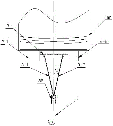
[0017] A coupler buffer, comprising a coupler 1, a left buffer 2-1 and a right buffer 2-2, the left buffer 2-1 and the right buffer 2-2 are arranged and installed in a car box along the width direction of a carriage 100. 100 at the bottom of both ends, the left buffer 2-1 is installed on the left side of the central axis of the car box, the right buffer 2-2 is installed on the right side of the central axis of the car box, and the coupler 1 is installed along the car box. The central axis of 100 is set at the bottom of both ends of the car box 100, and a limit push mechanism is installed between the left buffer 2-1 and the right buffer 2-2 and the coupler 1, and the limit push mechanism includes a left buffer. The push rod 3-1, the push rod 3-2, the lateral limiter 31 and the limiter 32 in the longitudinal direction, the left push rod 3-1 is installed on the left buffer 2-1 and the Between the coupler 1, the right push rod 3-2 is installed between the right buffer 2-2 and the ...

Embodiment 2

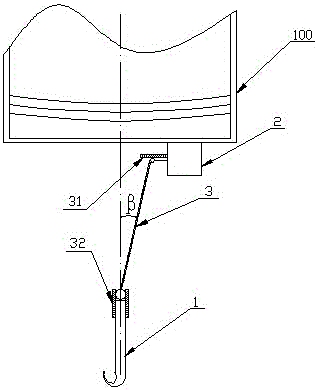
[0020] A coupler buffer includes a coupler 1 and a buffer 2, the buffer 2 is arranged and installed at the bottom of both ends of the car box 100 along the width direction of the car 100, and the coupler 1 is arranged along the central axis of the car box 100. At the bottom of the end, the buffer 2 is located on the right side of the central axis of the car box 100 , a limit push mechanism is installed between the buffer 2 and the coupler 3 , and the limit push mechanism includes a push rod 3 , a transverse limiter 31 and a longitudinal limiter 32, the push rod 3 is installed between the buffer 2 and the coupler 1, and the inner end of the push rod 3 is connected to the The compression end of the buffer 2 is connected, the outer end of the push rod 3 is connected with the hook tail of the coupler 1, and the inner end of the push rod 3 is assembled with the lateral limiter 31 , the inner end of the push rod 3 moves along the width direction of the carriage under the restriction...


PUM


Abstract

The invention discloses a coupler draft-gear, which comprises couplers and draft-gears. The coupler draft-gear is characterized in that the draft-gears are arranged at the bottoms of the two ends of a carriage along the width direction of the carriage, the couplers are arranged at the bottoms of the two ends of the carriage along a central axis of the carriage, the draft-gears are located on the left side or right side of the central axis of the carriage, a limited pushing mechanism is arranged between the coupler and the draft-gear, and the limited pushing mechanism can push the coupler to move along the central axis of the carriage and can push the draft-gear to be compressed along the width direction of the carriage. According to the coupler draft-gear disclosed by the invention, on the premise of not changing the maximum stroke and maximum resistance of the coupler, the capacity of the draft-gear is improved, and then the impact speed of the carriage is improved, so that when a train is running in limited operating conditions in the process of traction or braking, the draft-gear still can maintain a good cushioning effect, thereby improving the stationarity and safety of the train in the process of running.

Description

technical field [0001] The invention relates to the technical field of coupler buffer devices, in particular to a coupler buffer. Background technique [0002] The coupler buffer device is used to connect between the carriages of the train, transmit the traction force, the braking force and relieve the longitudinal impact. [0003] The coupler buffer device includes a coupler for connecting the carriages to each other and a coupler buffer for absorbing the impact energy of the carriages during the movement process to alleviate the longitudinal impact force between the carriages, and the coupler is connected with the carriage through the coupler buffer. [0004] The resistance force refers to the force in the process of deformation of the coupler buffer. Stroke refers to the amount of deformation produced by the coupler buffer under force. Capacity refers to the sum of the work done by the resistance force on the stroke of the coupler buffer during the full compression proc...

Claims


Application Information

Patent Timeline
Patent Type & Authority Patents(China)
IPC IPC(8): B61G9/04
CPCB61G9/04
Inventor 林立钿龚红霞王振
Owner ZHUZHOU TIMES NEW MATERIALS TECH
Why Eureka
Try Eureka