
Novel device of tethered balloon

A technology of tethered balloons and new devices, applied in the field of aerostats, can solve the problem of self-adjustment function of out-of-step cable discharge, unfavorable inflating and exhausting of vehicle-mounted balloons, and failure to realize "no touch" between the two ends of the cable discharge Commutation and other issues

Inactive Publication Date: 2015-05-20
QINGDAO FEIYU AEROSPACE SCI & TECH
View PDF0 Cites 16 Cited by
  • Summary
  • Abstract
  • Description
  • Claims
  • Application Information

AI Technical Summary

Problems solved by technology

Before the present invention, the cable rewinding and unwinding equipment that puts the optical cable on the cable reel generally adopts mechanical control or relay control for the reversing of the cable in the process of rewinding and unwinding the cable. The relay achieves the purpose of reversing by touching the limit switch or the reversing relay. Its defects: first, it cannot realize the "no-touch" reversing of the cable to and from the two ends; adjustment function
[0003] Furthermore, the backup compartment of the existing tethered balloon is set separately from the balloon mooring device, which is not conducive to convenient inflation and exhaust of the vehicle-mounted balloon.

Method used


Image

  • Novel device of tethered balloon
  • Novel device of tethered balloon
  • Novel device of tethered balloon

Examples


Embodiment Construction

[0015] The following is a specific embodiment of the present invention.

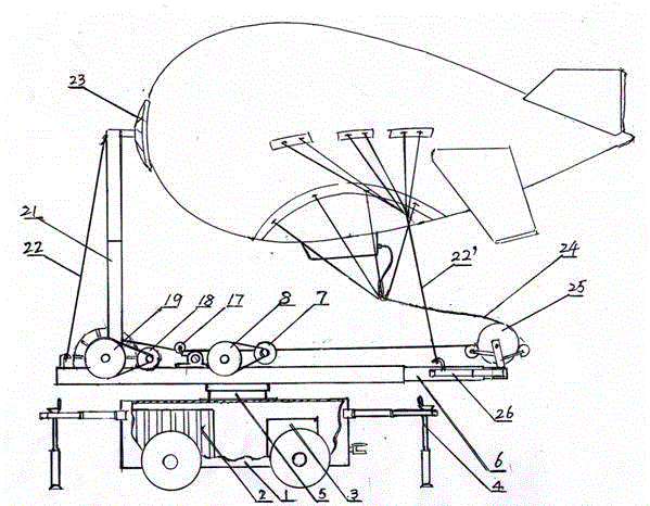
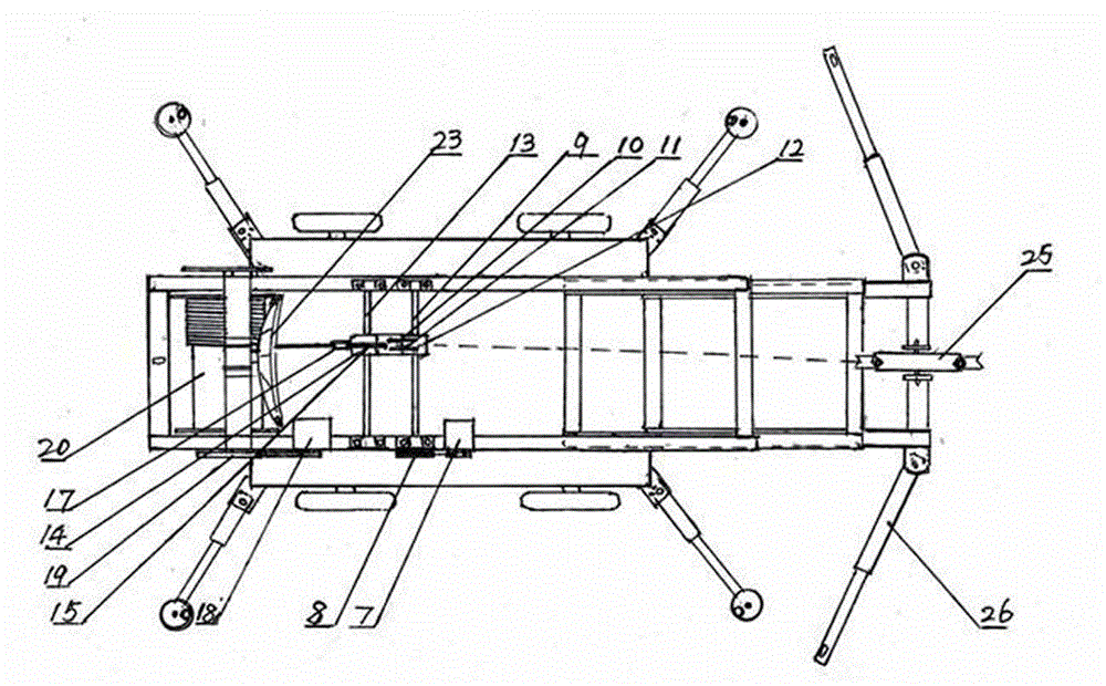
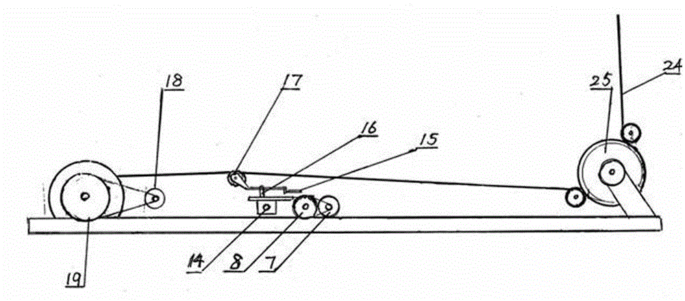
[0016] A new device for tethering balloons is attached figure 1 and 2 As shown, the telescopic outrigger 4 constitutes the support device, the turntable 5 constitutes the rotatable device of the workbench, and the telescopic horizontal workbench 6 is arranged on the turntable, and the foldable tower rod 21 stands on one end of the workbench, and the workbench The other end is provided with the first guide wheel 25 of the cable, and a cable receiving and releasing device is set on the workbench. Described receiving and unwinding device comprises horizontal leading screw 9, is contained in the movable leading screw nut car 12 on the leading screw, on the movable leading screw nut car parallel is installed with motor forward rotation switch 11 and motor reverse switch 10, is in The polished rod 13 that is arranged parallel to the leading screw before the leading screw, the slide seat 14 that can slide on ...


PUM


Abstract

A novel device of a tethered balloon mainly relates to the tethered balloon. The novel device of the tethered balloon comprises a supporting device, a rotary table, a work bench, a pole, a first guide roller, a cable deploying and retracting device and the tethered balloon, wherein the cable deploying and retracting device comprises a screw and a screw nut carrier; a motor forward-rotating switch, a motor reversely-rotating switch, a polished rod positioned in front of the screw, and a sliding seat installed on the polished rod are installed on the screw nut carrier; an oscillating bar is installed on a vertical shaft of the sliding seat; a second guide roller is installed at the front end of the oscillating bar; the sliding seat and the screw nut carrier are connected together by a connection plate; a cable rolling barrel is arranged in front of the second guide roller. The novel device of the tethered balloon has the advantages that the screw nut carrier is always maintained at a state at which the screw nut carrier is constantly adjusted and moves synchronically along with a twisted rope of the cable rolling barrel, in the out-of-step condition, cable rolling enters an out-of-step temporary adjustment process, then synchronization is quickly reached, the screw nut carrier always moves along with cable arrangement on the cable rolling barrel to realize "synchronous following-up", and thus the "out-of-step self-adjustment" function in the cable arrangement process is fulfilled. When the screw nut carrier is operated to one end of the screw and needs to return, as a cable enters a return stacking state, the tail end of the oscillating bar approaches the switch on the other side, and thus a motor is operated in a reverse direction.

Description

Technical field: [0001] The present invention relates to aerostats, and mainly to tethered balloons. Background technique: [0002] In the fields of national defense and meteorology, tethered balloons are widely used for emergency communication and meteorological data collection. The balloons used are tethered by optical cables. Transmit to the ground and access ground equipment. Before the present invention, the cable rewinding and unwinding equipment that puts the optical cable on the cable reel generally adopts mechanical control or relay control for the reversing of the cable in the process of rewinding and unwinding the cable. The relay achieves the purpose of reversing by touching the limit switch or the reversing relay. Its defects: first, it cannot realize the "no-touch" reversing of the cable to and from the two ends; Adjustment function. [0003] Furthermore, the reserve compartment of the existing tethered balloon is set separately from the balloon mooring devi...

Claims


Application Information

Patent Timeline
IPC IPC(8): B64B1/66
Inventor 于光谦
Owner QINGDAO FEIYU AEROSPACE SCI & TECH
Learn More