Sealing ring for reaction kettle

A sealing ring and reaction kettle technology, which is applied in the direction of engine sealing, engine components, mechanical equipment, etc., can solve the problems of easy damage to the lip of the seal, affect the sealing effect, and high cost of the sealing ring, so as to reduce the contact area and improve Compensation effect, effect of reducing frictional heat

Inactive Publication Date: 2015-05-20
DONGGUAN CLIMAX SEAL TECH
View PDF7 Cites 7 Cited by
  • Summary
  • Abstract
  • Description
  • Claims
  • Application Information

AI Technical Summary

Problems solved by technology

At the same time, the generated crystalline substances will also affect the sealing device of the rotating surface, scratch the sealing surface, affect the sealing effect, and seriously cause the sealing failure
The original reactor used rubber oil seals, and the residual crystalline substance easily fi

Method used


Image

  • Sealing ring for reaction kettle
  • Sealing ring for reaction kettle
  • Sealing ring for reaction kettle

Examples


Embodiment 1

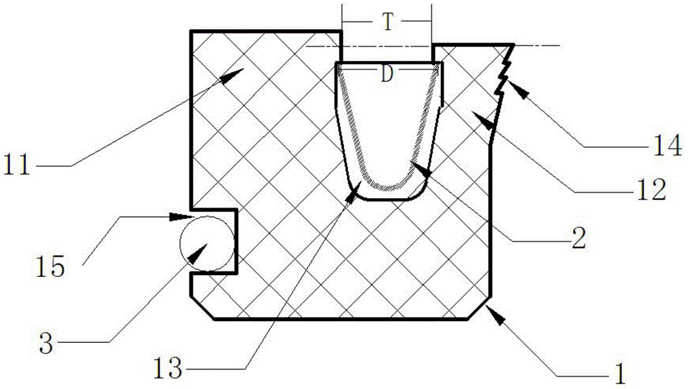
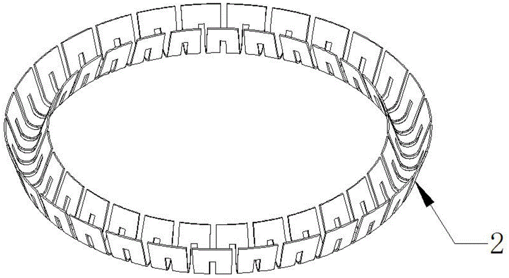
[0024] Please refer to figure 1 , figure 2 , a sealing ring for a reaction kettle, including a sealing ring body 1, the sealing ring body 1 includes an outer lip 11, an inner lip 12, an annular groove 13 is formed between the outer lip 11 and the inner lip 12 , the cross-section of the annular groove 13 is U-shaped, which also includes an elastic compensator, the elastic compensator is located in the annular groove 13 between the outer lip 11 and the inner lip 12, the inner lip 12 Multiple lips 14 are arranged on it.

[0025] In this embodiment, the elastic compensator is a U-shaped spring 2, the thickness of the outer lip 11 is greater than the thickness of the inner lip 12, and an annular groove 15 is provided on the outer side of the outer lip 11, and at the same time, the sealing The ring also includes an O-ring 3, and the O-ring 3 is arranged in the annular groove 15, so that during the sealing process, the sealing ring and the equipment are in closer contact to achiev...

Embodiment 2

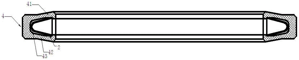
[0029] Please refer to image 3 , the difference between the second embodiment and the first embodiment is that the annular groove 13 in the first embodiment is rotated 90 degrees to the inner side of the sealing ring body 1 to obtain image 3 The surface view of the sealing ring of the second embodiment is shown, and the thickness of the outer lip 41 in this embodiment is equal to the thickness of the inner lip 42 . Other unmentioned components are the same as those described in Embodiment 1, and will not be repeated here.

Embodiment 3

[0031] Please refer to Figure 4 The difference between the third embodiment and the first embodiment is that the elastic compensator is a circular spring 6 , and the thickness of the outer lip 51 in this embodiment is equal to the thickness of the inner lip 52 . Other unmentioned components are the same as those described in Embodiment 1, and will not be repeated here.

[0032] In the above embodiments, the opening width T of the annular groove is smaller than the sectional diameter D of the elastic compensator to prevent the elastic compensator from falling out of the annular groove after installation, and the height of the outer lip is not lower than the height of the inner lip, that is The height of the outer lip is equal to or greater than that of the inner lip.


PUM


Abstract

The invention discloses a sealing ring for a reaction kettle. The sealing ring comprises a sealing ring body. The sealing ring body comprises an outer lip and an inner lip. An annular groove is formed between the outer lip and the inner lip. The sealing ring further comprises an elastic compensation part. The elastic compensation part is located in the annular groove between the outer lip and the inner lip. The inner lip is provided with a plurality of lip ports. By means of the design of the elastic compensation part, a spring provides pretightening force, and then a long-time sealing effect can be achieved; meanwhile, through design of the lip ports, the contact area is reduced, and accordingly the phenomenon of frictional heating is relieved. The sealing ring is low in cost, long in service life and better in sealing effect.

Description

technical field [0001] The invention relates to a sealing structure, in particular to a sealing ring applied to a reaction kettle. Background technique [0002] In the traditional chemical industry, in some resin synthesis reactors, due to structural requirements, the stirring shaft of the reactor is below the reactor, and some resins will travel to crystalline substances during the synthesis process, especially the part of the stirring shaft will generate heat due to rotation, which is more It will accelerate the survival of crystalline substances, and the generated crystalline substances will lead to increased friction and increased heat, which will further accelerate the formation of crystalline substances. At the same time, the generated crystalline material will also affect the sealing device of the rotating surface, scratch the sealing surface, affect the sealing effect, and seriously cause the sealing failure. The original reactor used rubber oil seals, and the resid...

Claims


Application Information

Patent Timeline
IPC IPC(8): F16J15/32F16J15/3208F16J15/3232F16J15/3284
CPCF16J15/3204
Inventor 周完成周安赵相田何贤富
Owner DONGGUAN CLIMAX SEAL TECH
Why Eureka
Try Eureka