The structure of the pressure equalizing angle valve of the nitrogen making device
A technology of angle valve and valve core, applied in valve device, valve operation/release device, lift valve, etc., can solve the problems of inconvenient angle valve failure, disadvantageous adsorption capacity, and high failure frequency.
- Summary
- Abstract
- Description
- Claims
- Application Information
AI Technical Summary
Problems solved by technology
Method used
Image
Examples
Embodiment 1
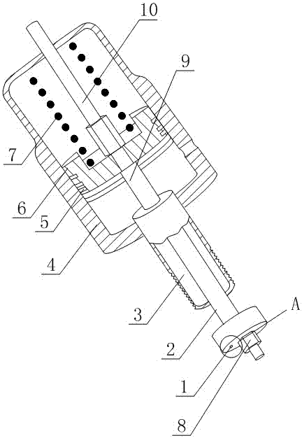
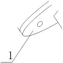
[0025] Such as figure 1 Shown, comprise valve core 1, valve rod 2 and cylinder 4, described cylinder 4 comprises cylinder body, the piston 6 that is arranged in cylinder body, piston rod 9 and return spring 7, the two ends of described valve rod 2 are respectively connected with One end of the valve core 1 and the piston rod 9 is fixedly connected, and the other end of the piston rod 9 is fixedly connected to one end of the piston 6, and also includes a piston rod extension 10. The piston 6 divides the cylinder into two cavities, close to the valve The cavity of the core 1 is a compressed air chamber, and the return spring 7 is arranged in another cavity. The piston rod extension 10 is partly located in the cavity provided with the return spring 7, and one end of the piston rod extension 10 is fixedly connected to On the piston 6, the other end of the extension part 10 of the piston rod is located outside the cylinder 4, and the valve core 1 is also provided with a through hol...
Embodiment 2
[0028] This embodiment is further improved on the basis of embodiment 1, as figure 1As shown, the cylinder 4 is a horizontal bar single-acting cylinder, and at least three annular sealing rings 5 are arranged along the side of the piston 6, and the annular sealing rings 5 are all O-rings.
[0029] In order to reduce the volume of the present invention and simplify the structure of the present invention, the piston rod 9 is integrated with the valve rod 2 , and the piston rod 9 is integrated with the piston rod extension 10 .
[0030] It also includes a spool nut 8, the valve stem 2 is in the shape of a stepped shaft with an external thread at one end, the spool 1 is provided with a central hole, the spool 1 is pierced on the valve stem 2, and the spool 1 and The valve stem 2 is fixed by a spool nut 8 .
[0031] The horizontal bar single-acting cylinder has a simple structure and low cost; at least three annular sealing rings 5 are provided to further strengthen the seal...
Embodiment 3
[0034] The present embodiment is further limited on the basis of embodiment 2, as figure 1 As shown, it also includes a cylindrical fixed sleeve 3, one end of the fixed sleeve 3 is fixedly connected to the cylinder body, the other end of the fixed sleeve 3 is provided with external threads, and the center line of the fixed sleeve 3 is in line with the valve stem 2 The center lines are collinear, and the fixed sleeve 3 is located between the valve core 1 and the cylinder body.
[0035] The external thread is a fine pitch thread.
[0036] The fixed sleeve 3 provided is used for the connection of the present invention with the valve seat, that is, the valve seat is provided with an internal thread hole matching the external thread, and the fixed sleeve 3 and the valve seat are threaded to facilitate adjustment of the valve core and the valve seat in the closed state. The compressive stress between the seats ensures the sealing effect when the pressure equalizing tube is disconne...
PUM
 Abstract
Description
Claims
Application Information
 - R&D
- Intellectual Property
- Life Sciences
- Materials
- Tech Scout
- Unparalleled Data Quality
- Higher Quality Content
- 60% Fewer Hallucinations
Browse by: Latest US Patents, China's latest patents, Technical Efficacy Thesaurus, Application Domain, Technology Topic, Popular Technical Reports.
© 2025 PatSnap. All rights reserved.Legal|Privacy policy|Modern Slavery Act Transparency Statement|Sitemap|About US| Contact US: help@patsnap.com


