
IVF (in-vitro fertilization) laboratory instrument trolley

A technology for laboratories and trucks, which is applied in the direction of biochemical instruments, supporting machines, machine tables/supports, etc. It can solve the problems of not being universal, scattered external power supply interfaces and gas pipeline interfaces, and being unable to move at will, and achieve reasonable design effects.

Active Publication Date: 2015-05-20
陈子江 +1
View PDF6 Cites 2 Cited by
  • Summary
  • Abstract
  • Description
  • Claims
  • Application Information

AI Technical Summary

Problems solved by technology

This has resulted in the phenomenon that in the actual use process, the experimental facilities are complicated and the models are varied.
[0003] In addition, a large number of external power supply interfaces and gas pipeline interfaces are scattered outside, which not only gives people a visually messy feeling, but also increases the chance of accidental touch, posing a certain safety hazard
If each type of incubator is independently equipped with experimental tables, fixed tables, etc., there will be disadvantages such as low space utilization and inability to move freely once fixed. Since the power supply and gas pipelines have unique interfaces, this kind of equipment cannot universal

Method used


Image

  • IVF (in-vitro fertilization) laboratory instrument trolley
  • IVF (in-vitro fertilization) laboratory instrument trolley
  • IVF (in-vitro fertilization) laboratory instrument trolley

Examples


Embodiment 1

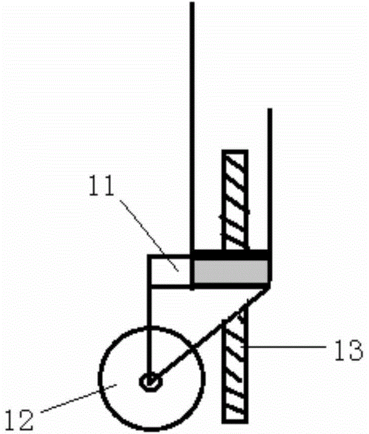
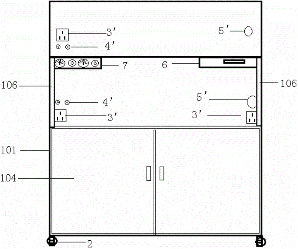
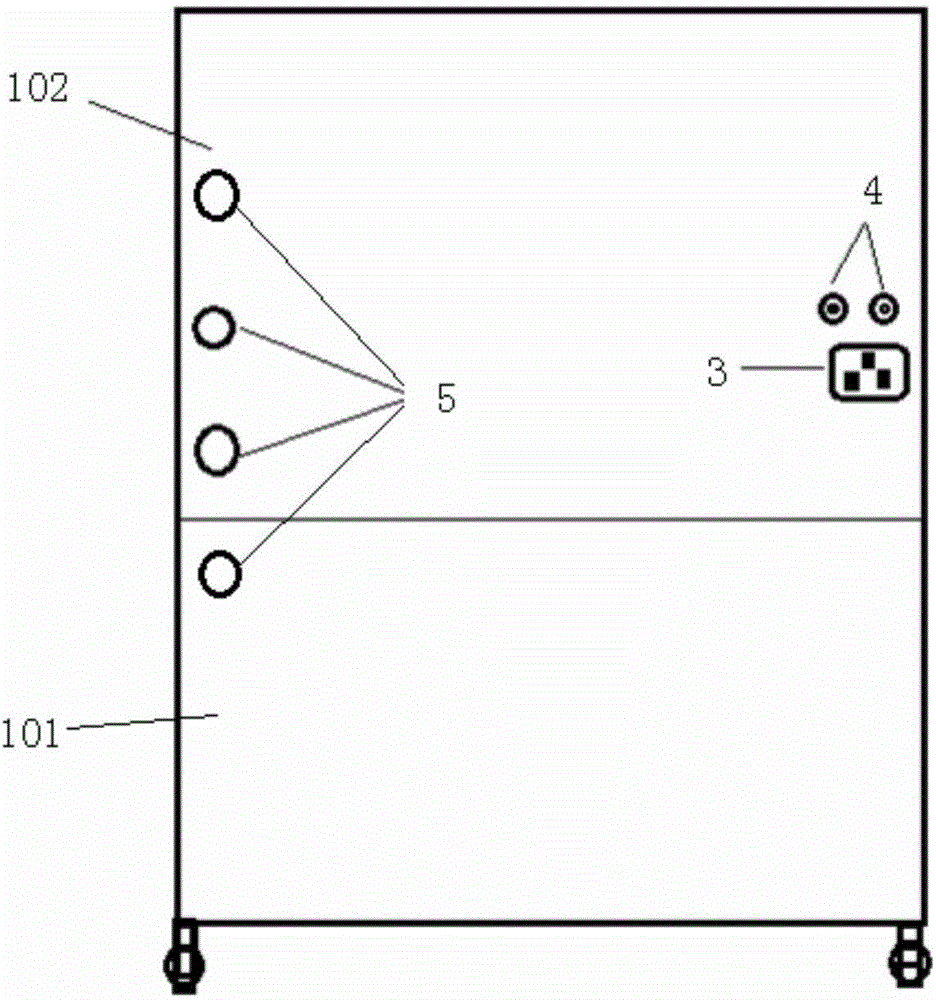
[0040] like Figures 2 to 5 As shown in the figure, an IVF laboratory instrument rack includes a vehicle main body, which mainly includes a bottom box 101, a back plate 102 and a bearing plate 103, and a roller mechanism 2 is installed at the bottom four corners of the bottom box 101, Can be easily moved. Further, the bottom box is closed on all four sides and can be used as a storage space, and a box door 104 is installed in the front. The box can be loaded with experimental instruments, computers, consumables or other tools, wiring, pipelines, etc., which can effectively save external space. And the appearance is simple and neat. Furthermore, the upper panel 105 of the bottom box can be made slightly larger, and the front end extends out of the box body, so that the area of ​​the table can be increased, more things can be placed or it is convenient to carry out experimental operations on it.

[0041]A rear panel 102 is erected along the rear side of the bottom box 101 , an...

Embodiment 2

[0057] like Figures 6 to 10 As shown, an IVF laboratory benchtop instrument rack includes a main body of the rack, the rack body includes a rack and four support columns 201 at the four corners of the bottom, and a roller mechanism 2 is installed at the bottom of each support column 201 to make the rack Become a movable trolley. The height of the rollers can be adjusted, for example, by means of bolts, so that when the rollers are raised, the vehicle body can be fixed on the ground by means of a support column, and when the rollers land on the ground, the vehicle body can be moved.

[0058] The top of the main body of the carriage has an upper panel 202, and an enclosure 203 may be provided at the edge of the upper panel, so as to make the instruments and equipment placed on the upper panel safer to prevent falling. A computer, a mouse and keyboard, an incubator, etc. can be placed on the upper panel 202 . There are many ways to set the enclosure 203, for example, setting e...


PUM


Abstract

The invention discloses an IVF (in-vitro fertilization) laboratory instrument trolley available in both a tabletop type and a table type. The IVF laboratory instrument trolley comprises a trolley body, a relief box, a power access interface, a gas pipe access interface and rollers. The IVF laboratory instrument trolley is reasonable in design and safe and solid and matches with culture boxes of all types and specifications, indoor space can be maximally utilized, a power line and a gas pipeline are highly integrated in the trolley body, and the trolley is attractive and simple in appearance and high in adaptability and is fixable and movable owing to the rollers.

Description

technical field [0001] The invention relates to a storage rack cart for various types of incubators and instruments in an IVF laboratory. Background technique [0002] At present, there are various incubators used for embryo cultivation in IVF laboratories, and there are great differences in various brands, sizes and types. . This results in the phenomenon that the experimental facilities are cumbersome and complex and the models are varied in the actual use process. [0003] In addition, a large number of external power supply interfaces and gas pipeline interfaces are scattered outside, which not only gives people a visually cluttered feeling, but also increases the probability of accidental touches, posing certain safety hazards. If each type of incubator is independently equipped with a laboratory table, a fixed table, etc., there are disadvantages such as low space utilization rate and inability to move freely once fixed. Since the power supply and gas pipeline have u...

Claims


Application Information

Patent Timeline
IPC IPC(8): F16M11/26C12M3/00
Inventor 陈子江吴克良李城马金龙
Owner 陈子江
Learn More