
Detection and positioning method of launch vehicle motion signal during propellant filling process

A technology of launch vehicles and motion signals, applied in the field of signal detection, can solve the problems of low sampling frequency of the system, errors, and interference of camera visual positioning, and achieve the effect of improving detection accuracy, improving real-time performance, and fast sampling frequency

Inactive Publication Date: 2017-08-29
NANJING UNIV OF SCI & TECH +1
View PDF4 Cites 0 Cited by
  • Summary
  • Abstract
  • Description
  • Claims
  • Application Information

AI Technical Summary

Problems solved by technology

If camera vision positioning is used, at least two cameras are required to form a stereo vision detection system, but it is difficult to balance the field of view of stereo vision and its target positioning accuracy, and the controller needs to process a large amount of image data, which leads to system Low sampling frequency is not conducive to real-time tracking. At the same time, the arc surface of the arrow body will interfere with the visual positioning of the camera, resulting in large errors

Method used


Image

  • Detection and positioning method of launch vehicle motion signal during propellant filling process
  • Detection and positioning method of launch vehicle motion signal during propellant filling process

Examples


Embodiment

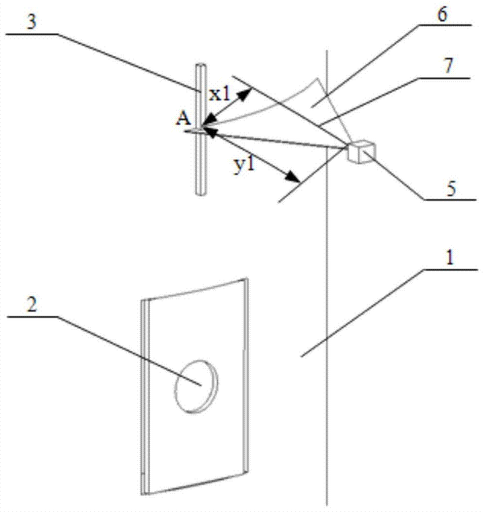
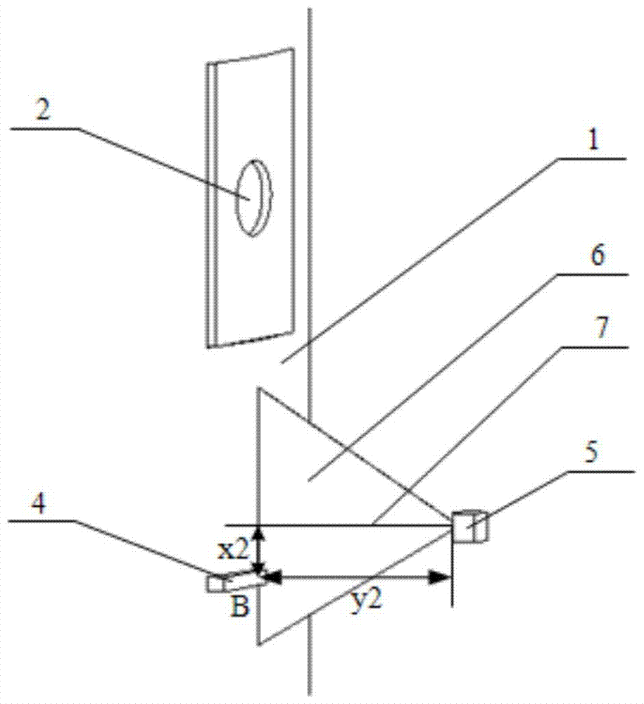
[0026] combine figure 1 and figure 2 :

[0027] A method for detecting motion signals of a launch vehicle during propellant filling, comprising the following steps:

[0028] Step 1: Set two mutually perpendicular raised marks on the surface of the rocket body 1, one of the raised marks is parallel to the axial direction of the rocket body 1, and its extension line passes through the center line of the rocket body filling valve 2, which is a vertical raised sign 3 and another horizontal raised sign 4;

[0029] Step 2: A 2D laser displacement sensor 5 is installed at the position corresponding to the raised mark, and the laser sector 6 of the 2D laser displacement sensor 5 is perpendicular to the raised mark of the arrow body, and ensures that the center line 7 of the field of view of the 2D laser displacement sensor 5 is in line with the The raised mark intersects, the distance between the 2D laser displacement sensor 5 and the raised mark is d, and it is ensured that the r...


PUM


Abstract

The invention discloses a method for detecting and locating a motion signal of a carrier rocket in the propellant charging process. The method comprises the steps of setting a bulge mark, locating a 2D laser displacement sensor, acquiring data and determining motion displacement by virtue of the 2D laser displacement sensor, and locating according to the displacement. The method is high in detection precision, high in sampling frequency and good in real-time property.

Description

technical field [0001] The invention belongs to the technical field of signal detection, in particular to a method for detecting and locating motion signals of a launch vehicle during the propellant filling process. Background technique [0002] The launch vehicle needs to be filled with various propellants before launch, but during the process of propellant filling, the tower opens the shutters, and the rocket body will vibrate slightly under the influence of wind load. In order to ensure the reliability of propellant filling, the connector needs to move with the rocket body, so it is necessary to detect the motion information of the rocket body in space in real time. If camera vision positioning is used, at least two cameras are required to form a stereo vision detection system, but it is difficult to balance the field of view of stereo vision and its target positioning accuracy, and the controller needs to process a large amount of image data, which leads to system The l...

Claims


Application Information

Patent Timeline
Patent Type & Authority Patents(China)
IPC IPC(8): G01B11/00G01B11/02
Inventor 李志刚李宗涛黄超赵纯王志翔徐华何庆杜光华张亮孟长建于存贵张鑫宋涛玄柳王正要
Owner NANJING UNIV OF SCI & TECH
Learn More